Coleman Mach Thermostat Wiring Diagram: Wiring Color Codes
Air conditioners or heat pumps require only a small amount of electricity to run. With the proper Coleman Mach thermostat wiring Diagram, you can acquire that energy and have a working unit. Changing out an old one with a new one doesn’t necessitate a mastery of complex wiring diagrams.
Read our article to learn more about a wiring diagram, color code, and how to hook it up. Spend some time thinking about how this data will aid you in wiring your thermostat correctly and how much time it will save you.
So, let’s get into the details without wasting any more time!
Table of Contents
How do You Hook up a Coleman Thermostat?
Assuming you know your way around thermostat wiring diagrams, this job will go quickly and easily. In order to avoid making any blunders, you will need to take things gently. In addition, you should avoid causing a short circuit while trying to resolve the underlying issue.
Thermostat wirings shouldn’t be too challenging, thanks to the color-coded method. If a wire has a particular color, simply connect it to the same marked socket.
The only issue you might have is that the ground wire is different from what you’re used to seeing. Not seeing the ground connections familiar can make matters more difficult. Xanax for anxiety https://mountainviewmedicalclinic.com/xanax/
Get someone who doesn’t mind working with electricity if you’d rather not. A lot of focus is needed to ensure no mistakes are made in the thermostat wiring.
What Color Wire Goes Where on a Thermostat?

The white wire should be connected to W2 AUX, and the brown wire should be connected to W, which has two symbols under it. The Y terminal is linked to the yellow wire, whereas the Y2 terminal is linked to the orange wire.
While the blue one should be connected to the C terminal, the red one should go to RH. Next, connect the green wire to the G terminal. It appears that, with the exception of the yellow wire, the green wire is the only other viable connection.
Wiring Color Codes for Coleman RV Thermostat
Coleman thermostats come in a wide range of configurations, each with its own control mechanism, power input voltage, and heating/cooling possibilities. There are two primary kinds of designs: digital and analog.
Each of those can be further broken down into two distinct categories: heat/cool and cool-only. Additional input power possibilities for digital devices include 12VDC, 24DC, and AC.
Conversely, you can tailor your design choice to the specifications of your car in terms of both the voltage and climate control systems.
Digital Display
There are five to nine wires, and they are all color-coded, so you know exactly what each one does on the Coleman RV thermostat with a digital display and temperature settings.
Single-Stage 12VDC Thermostat Heat Pump
To operate a 1-stage heat pump with a 12VDC digital thermostat that can both heat and cool, you will need to connect the following seven wires:
Sr. # | Color codes | Color | Function |
01 | GL | Gray | Fan Low Speed |
02 | GH | Green | Fan High Speed |
03 | WhP | White/Black | Heat Pump |
04 | Y | Yellow | AC Compressor |
05 | R | Red | The Positive Terminal of the Battery (+12VDC) |
06 | B | Blue | Negative Terminal or Ground (-12VDC) |
07 | WF | White | Furnace |
A similar capability, requiring 9 wires, is available on various Coleman thermostat models.
Two other wires, colored white and green (white with green stripes), is connected to temperature sensors in other rooms.
1-Stage 24V
The 24VDC or AC input digital thermostat features a heat/cool setting. It includes an automatic on/off fan with no manual control over high or low speeds.
Consequently, it requires a total of 5 wires: 1 for the fan, 1 for the compressor, 1 for the heat, 1 for the 24V cold, and 1 for the 24V hot. As with the earlier described models, the color scheme follows a standard.
2-Stage 12VDC
The air conditioner and furnace can be controlled separately or together using its two-stage interface. The first, highest setting, is for extremely hot or cold weather, while the second, lowest, is for moderate weather with somewhat constant temperature shifts.
The Coleman 2-stage thermostat includes two wired connections for independent temperature regulation (one for heating and one for cooling), runs on 12VDC, and features auto and ON fan modes with variable speed control.
You’ll find nine wires in one of its two connectors, and in the other, you’ll find three or four. Both connectors follow the following color scheme:
First Connector
Sr. # | Color codes | Color | Function |
01 | G | Gray | Freeze or High Settings for AC |
02 | R | Red | 12VDC Power |
03 | G | Gray | Second Terminal for Freeze |
04 | B | Blue | -12VDC Power (negative terminal) |
05 | Y | Yellow | AC Compressor Terminal 1 |
06 | O | Orange | AC Compressor Terminal 2 |
07 | B | Black | Fan High-Speed Setting |
08 | WhB | White/Black | Electric Heater Control |
09 | P | Purple | Indoor Fan Low Speed |
Second Connector
Sr. # | Color codes | Color | Function |
01 | RWh | Red/White | +12VDC |
02 | BWh | Blue/White | -12VDC |
03 | Wh | White | A Heat Pump or Gas Furnace Low Control for RV |
04 | OWh | Orange/White | A Heat Pump or Gas Furnace High Control for RV |
In the aforementioned table, the function and color of the wire labeled sr#1 and sr#8 can vary with the type of digital gadget used.
In addition, a version is offered where the fourth connection point in the second connector is absent; This version just has one knob for operating the camper’s gas furnace.
Analog Readout
In addition to digital models, Coleman offers analog thermostats with heat/cool and cool-only controls. Adjusting the temperature is as simple as sliding a knob on an analog scale.
Plus, they can’t be used without a 12VDC power source. 24VDC-powered variants of some designs are also on the market. The rest of their operation concept and setup procedure is the same.
Analog Thermostat with Heat & Cool Control with 12VDC Power
It accepts 12VDC power from an external source and has ports for plumbing in HVAC compressors and gas/electric heaters.
The temperature can be set in either a high or low setting, and the fan speed can be adjusted up or down. Colors in this analog model are assigned as follows:
Sr. # | Color codes | Function |
01 | Green | High Fan Speed Control |
02 | Gray | Low Fan Speed Control |
03 | White | Eclectic or Gas Heating Element Control |
04 | Yellow | AC Compressor for Cool Settings |
05 | Red | The Positive Terminal of the Battery (+12VDC) |
06 | Blue | Negative Terminal or Ground (-12VDC) |
Analog Thermostat with Cool Only Option 12VDC Input Power
Only use a Coleman air conditioner, which requires a 12VDC power input. There is no way to regulate the temperature.
The only difference from the preceding design is the absence of the white wire used for temperature regulation.
Analog Thermostat 24Volt
It operates on 24V input power so you may use it with any RV power supply.
High and low-temperature settings are available, as are auto/on fan modes with no speed regulation. For RV use, the five wires are color-coded as follows:
Sr. # | Color Code | Color | Function |
01 | RH | Red/White | 24VDC or AC Input for Heat Control |
02 | R | Red | 24VDC or AC Input for Cool Settings |
03 | G | Green | Fan Output for ON/Auto Control |
04 | Y | Yellow | AC Compressor Output |
05 | W | White | Heat Output |
Proper Color Coding Scheme with the Thermostat in RV
When installing a Coleman thermostat in an RV, it’s important to follow the manufacturer’s recommended color-coding system for added safety.
Air conditioning and fan wiring modifications become obsolete with time.
It’s useful when updating the unit or installing a replacement appliance for the cabin’s climate control. A short circuit can damage the air conditioner, RV furnace, or thermostat if the wires are connected incorrectly.
Power Requirements of the Coleman Thermostats
The energy consumption of Coleman thermostats varies from one model to the next. Most of them can be powered by a 12VDC source, such as a battery.
All versions use the same input power color conventions, with a red wire connecting the positive terminal and a blue wire connecting the negative terminal.
There are additional 24 Volt variants, which can be powered by a DC or AC supply of the same voltage.
Wire Gauge to Use for Wiring Diagrams of the RV Coleman Thermostat
In addition, Coleman produces low-voltage switch wires of a specific gauge for use in HVAC systems.
To ensure proper communication between your Coleman Mach thermostat and its controls, you should use an 18-gauge wire with 5-8 conductors and insulation in a colour scheme that matches the thermostats.
Sources of Finding Color Coding Scheme of RV Thermostat
Coleman is an industry-leading producer of air conditioners, heating strips, and other cabin temperature control systems for recreational vehicles.
All of its goods come with an accompanying guide for setting them up or using them. Therefore, it is the best and most reliable place to look for the thermostat model’s color coding system.
Secondly, the thermostat wiring schematic and standard colors for various purposes can be found at Trucksauthority.com. It will be useful for defunct models for which no information is currently accessible.
Wiring Diagrams
7330-730 & 8330-733 Series Cool Only Ducted Ceiling Plenums
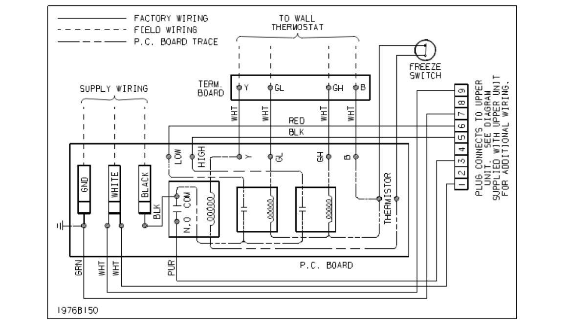
7330-735, 7330-736 & 8330-735 Series Heat/ Cool Ducted Ceiling Plenums
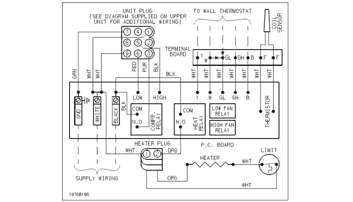
7330-720 & 8330-723 Series Cool Only Remote Free Delivery Ceiling Plenums
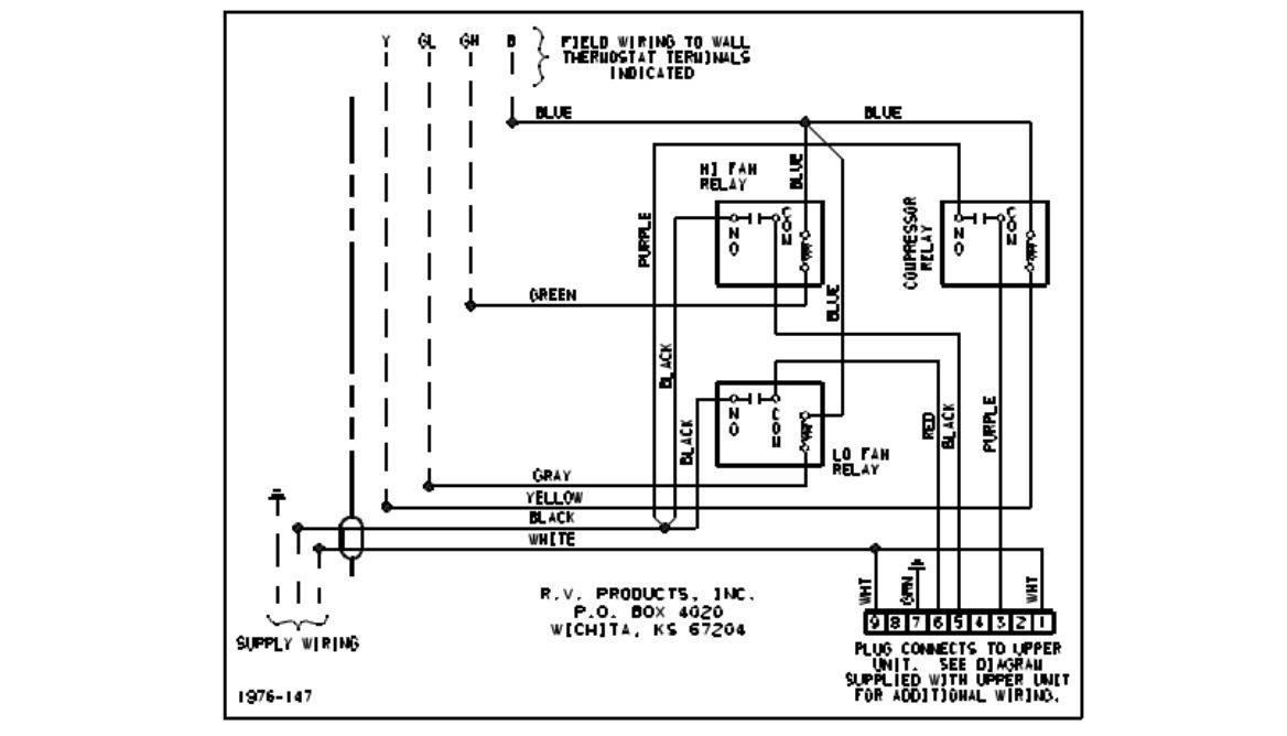
7330-725, 7330-726 & 8330-725 Series Heat/Cool Remote Free Delivery Ceiling Plenums

FAQ
What are the S1 and S2 terminals on a thermostat?
The exterior temperature is transmitted to the thermostat through the S1 and S2 cables, which run immediately outdoors.
What are the 7 thermostat wires?
1. Red Wire: Power (24V input in most cases).
2. Green Wire: Fan
3. White Wire: Heating
4. Blue: Cooling
5. Rh: Heating Power
6. Rc: Cooling Power
What happens if you wire a 2-wire thermostat wrong?
Electric shock is one possible repercussion of faulty installation. Whether it’s the thermostat itself, the thermostat wiring, or the air conditioner or furnace, all of these things might be damaged.
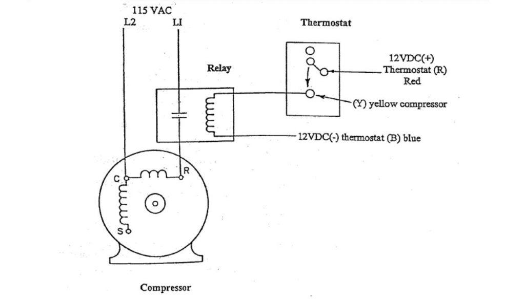
Which is the hot wire L1 or L2?
When connecting the new motor, the “hot” wire must go to L1, and the neutral wire must go to L2. Be sure to adjust the dial for 115 volts rather than the default 230 volts.
Conclusion
If you’re not confident in your ability to wire your Coleman Mach Thermostat, you should hire an expert. Examining the thermostat wiring diagram might be a bit of a headache, but the color scheme we discussed should clarify things.
Was this article helpful for you? After analyzing all the color codes and expertise needed to carry out this task, will you DIY or hire an expert? Let us know in the comment section below or ask about anything you have in mind related to Coleman diagrams!

Asen is the owner and main contributor of Camper Life. He is a full-time RV traveler since 2018. He loves camping in nature, fishing, and spending time with his family.
Striving to provide the most valuable information about campers and RVs, he shares everything he learned over the years.
That’s why Camper Life is one of the best sources to find information about RV traveling and living.


