6 Pin to 7 Pin Trailer Wiring Diagram: 7 Color Wire Notes Explained
Getting ready to tow involves a lot of moving parts. There is plenty of essential specifics to sort out. But, it is possible via a proper understanding of the 6 pin to 7 pin trailer wiring diagram.
Checking the functionality of your trailer’s electrical components is one of the major aspects. Read on to learn about the 4 types of connectors, different wiring notes along with their preferred sizes, and a color code wiring diagram for your better understanding.
Let’s get started!
Table of Contents
An Insight Into 6 Pin To 7 Pin Trailer Wiring
Online resources offer multiple trailer wiring diagrams that cater to different trailer wiring standards. However, it is crucial to avoid taking shortcuts since each standard serves a specific purpose.
It’s essential to ensure that your trailer adheres to the prescribed guidelines and doesn’t become an unconventional, haphazard creation. By following the guidelines, you can ensure that your trailer’s electrical requirements are met. These are the minimum requirements:
- Brake lights
- Turn signals
- Tail lights
Additionally, some trailers may require:
- Side markers
- Running lights
While some braking systems may need the power to operate electronic brakes or to disengage hydraulic brakes while reversing.
For a better understanding you can see the video here:
How a 7-Way Plug Works With 6 Wires
Older trailers typically have a 6-pin plug due to the limitations of the time they were manufactured. Conversely, newer ones come with 7-pin connectors to tow trailers.
- When connecting the two, one of the seven pins on the adapter might not work, but the connection should still be possible.
- It is crucial to comprehend the purpose of each pin on the trailer side to ensure a successful connection.
- To avoid any problems, you can test each pin or wire of the trailer separately using a 12-volt trailer battery charging if a critical component is not receiving power.
6-Pin And 7-Pin Trailer Connector: 2 Differences
Here is an insight into the differences:

Backup Light Connection
The only difference between the 6-pin trailer and 7-pin trailer connectors is that the former lacks a backup light connection. Meanwhile, the latter has it. Whether this matters or not is determined by your state’s regulations.
If it is legal to tow a trailer in your state, all you need is the appropriate adapter to connect your trailer. Adapters for both 6-pin and 7-pin connectors are available at:
- On Amazon
- Hardware shops
- Big-box stores
- Other online retailers
Budget
The price range for these adapters varies depending on where you purchase them. You can easily obtain these adapters from RV accessories and parts retailers. If you’re uncertain, take a photo of the trailer connector with your phone and show it to the cashier for assistance.
Trailer Wiring Connectors
The number of pins on a trailer connector determines the ability to power various accessories, such as backup lights, electronic trailer brake controller, and 12V power source for brake or interior trailer lights.
- Connectors with four to seven pins can provide power for these features.
- Choosing a trailer connector with the appropriate number of pins required to operate your trailer is necessary.
- If the connector is located underneath the chassis, a mounting bracket is required to secure it to the car.
- Failure to secure the connection properly may result in it dangling and causing damage.
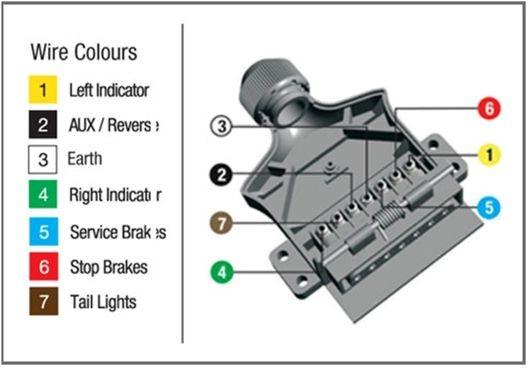
See the table below to learn about the main lighting functions of each colored wire!

4-Way Connectors
4-way connectors are commonly used in towing devices and allow for the connection of the ground wire and the three primary lights:
- Running lights
- Turn Signal
- Brake lights.

5-Way Connectors
A 5-way trailer connector, with one extra pin in addition to the ground wire and the three primary lights, is typically used for trailers with hydraulic or surge electric brakes. The extra pin is connected to the backup lights to release the electric trailer brakes when the car is in reverse.

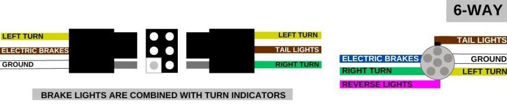
6-Way Connectors
For electric brakes and a 12-volt “hot” lead, the 6-way pin trailer connector is typically used. The ground and the two extra pins power these features, in addition to the three primary lighting tasks.
Horse trailers usually use the circular 6-way connection, while campers use the 6-way square connection.
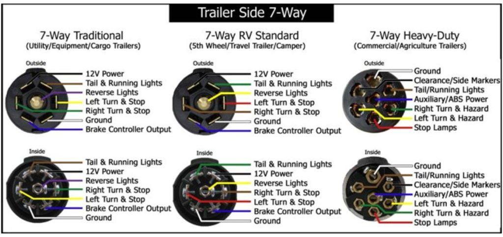
7-Way Connectors
7-way connectors have additional pins for:
- Electronic brakes
- A 12-volt hot wire
- Backup lights
In addition to the three primary lighting tasks. The 7-pin trailer connector can be split into two halves, with one half having flat pins or blades and the other half having rounded pins.
However, the round-shaped pin is rarely used. The 7-way trailer connector with flat pins or blades is widely used and is typically found on modern vehicles and SUVs equipped with a factory trailer hitch.

Mounting Your Trailer Wiring Harness
Storing the 4-pole trailer hookup in the trunk or cargo compartment of a car or SUV when not in use is a popular practice. This protects the connection from environmental elements and accidental damage, ensuring its longevity.
Simply remove the connection and lock the trunk or back door when you need to tow. The rubber weather strip that provides a door seal prevents the wire from being pinched.
Related Problems to Converter Explained
We explain the common reasons that too many amps are being drawn through the converter box and potentially causing damage below.
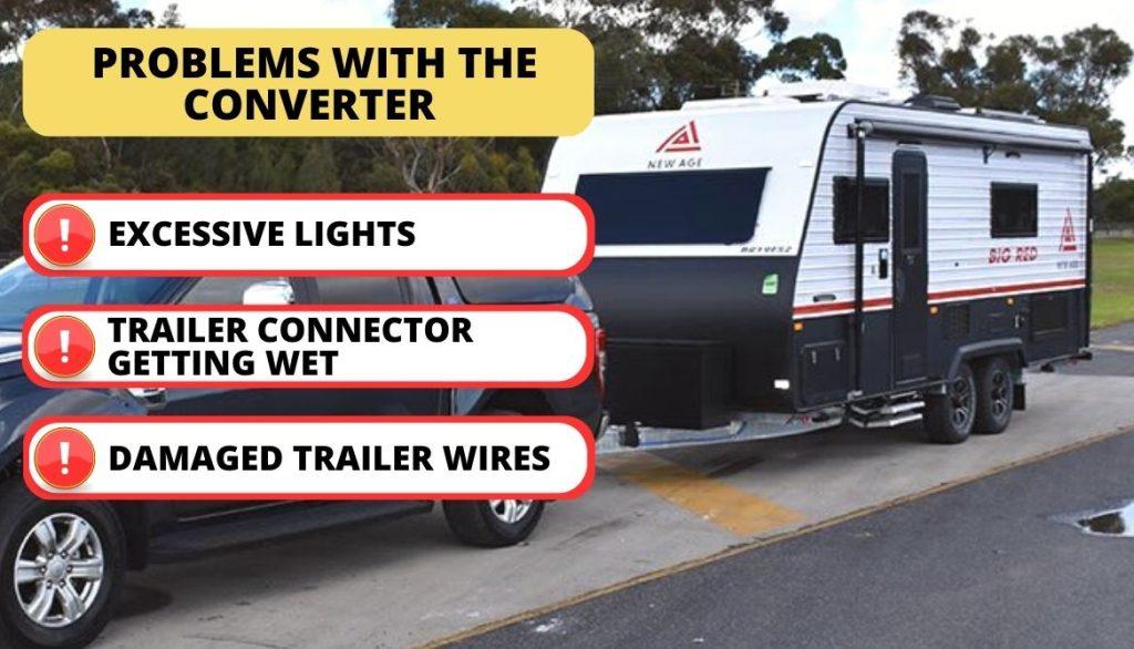
Excessive Lights
Each typical incandescent taillight on a vehicle requires approximately:
- 2 amps of electrical current,
- While each side marker light typically draws around 0.5 amps.
Note that many converters are designed to handle up to 4 amps of current, sufficient for powering a few lights.
Regardless, it’s worth noting that when using a conventional converter, only one brake light per side is permitted. Meaning if a vehicle has multiple brake lights on one side like some newer models, a different type of converter or wiring may be necessary.
Water
Trailer wiring connections are prone to getting wet. When water enters the trailer connector, it can cause short circuits in all four trailer wires. It can lead to an excessive amount of current being drawn through the converter box.
Amperage Overload
This can lead to the converter box getting damaged by a spark due to an overload of amperage. One common scenario where this can occur is when a boat is being towed behind a car and the trailer wiring is reversed into the water without disconnecting the wire.
Precaution
It’s always a good idea to disconnect the trailer’s wiring and trailer plug before reversing into the water. In case of rain or car washing, using a cover can help keep water out of the trailer connector and prevent moisture from causing electrical problems.
Bare Wires Causing Issues
When too many electrical components are drawing power from the converter box, it can become overloaded, potentially causing issues with the trailer’s lighting system. One of the common reasons for this issue is due to wear and tear on the trailer wires.

Damaged Coating
The coating on the trailer wiring diagram becomes damaged in areas where the wires run over the suspension or connect to the taillights. Wires that are loosely strung on the trailer run the risk of getting crushed between the trailer frame and the suspension U-bolts.
As a result, the wires can become frayed or damaged, causing issues with the trailer’s lighting.
Precaution
To prevent such issues, it’s crucial to inspect the trailer wires regularly for wear and fraying. If any damage is found, the wires should be replaced immediately. Keeping the trailer’s wiring in good condition can avoid potential safety hazards and ensure a smooth, trouble-free journey.
3 Best Ways for Installing Trailer Wiring on Vehicle
For the safe and effective operation of a trailer’s electrical systems, a reliable and properly installed trailer wiring harness is essential. This harness allows the trailer wiring diagram to be linked to the towing vehicle’s electrical system.
It provides power to the:
- Trailer’s lights
- Electric trailer brakes
- Other necessary components
However, not all vehicles come equipped with functional trailer wiring, making it difficult to connect the two systems. The good news is that there are various options available to customize your vehicle’s wiring setup to suit your specific needs.
Option A: Custom Wiring Installation

For connecting your car to a trailer, there’s nothing more convenient than a professionally installed system. While a 4-way flat is a common option, a custom wire harness, also referred to as a “T-connector,” is tailored to fit a specific vehicle. It can be easily plugged in.
Each CURT custom wiring kit comes equipped with vehicle-specific connectors and, if required, an electrical converter to ensure an effortless installation process.
Custom Wiring Harnesses
A custom wire harness with multiple connectors that ‘T’ into the vehicle’s taillight assembly is typically used for the standard trailer wiring diagram light hookup. This bespoke wiring system can draw power from the taillights or a direct battery connection.
Unlike splicing or soldering, custom wire harnesses generally have two or more connection points and do not require these methods.
Custom Wiring Connectors
While the trailer wiring connector on certain cars may deviate from the standard, the vehicle manufacturer may have provided a designated socket for this purpose. By creating a custom wiring connector that plugs into this factory socket, you can obtain a standard trailer wiring diagram connector.
Option B: Taillight Converter Splice-in Wiring

If your specific make and model does not have specialized wiring available, you may need to use a taillight converter to transform your vehicle’s existing taillight wire into a connector for a trailer wiring light harness.
The standard trailer wiring plug connector is a 4-way flat, which can be attained by installing a taillight converter or electrical converter in your vehicle. The converter modifies the complex electrical setup of your vehicle to enable communication with the simpler setup of the trailer.
Option C: Replacement Vehicle and Trailer Plug Wiring

If you have a damaged or non-functioning trailer wiring plug on your car or trailer, CURT splice-in plugs and sockets can be utilized for repair.
Trailer wiring plugs and car sockets are standard configurations that can be interchanged and spliced into an existing system. Below are several trailer light wiring diagrams to choose from, to determine the one that best matches your current setup.
Trailer Wiring Diagram: Important Notes
Do you find it difficult to recognize different color codes? Well, your issue is resolved now! Read about various wiring notes below and learn about their sizes along with a few unique factors.
Trailer Brakes and Wire Size
Wire diameters are available in various sizes, typically measured in “Gauge,” with smaller numbers representing thinner wires.
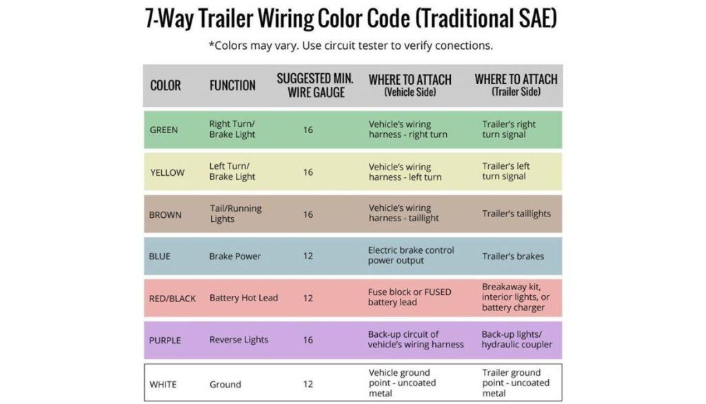
- For lighting purposes, a suggested gauge of 16 or larger is appropriate.
- While power-hungry equipment such as electric trailer brakes may require a stronger wire size of 14 or 12 gauge.
This applies similarly to auxiliary power. Low-power bulbs such as LED lights consume minimal energy, even in large numbers. As a result, smaller wire gauges may be acceptable for lighting applications.
Lights
Our top recommendation for trailer wiring lights is to choose LED lights that are capable of withstanding being submerged in water. While most trailers may not go underwater, they are likely to become wet from heavy rain or washing.
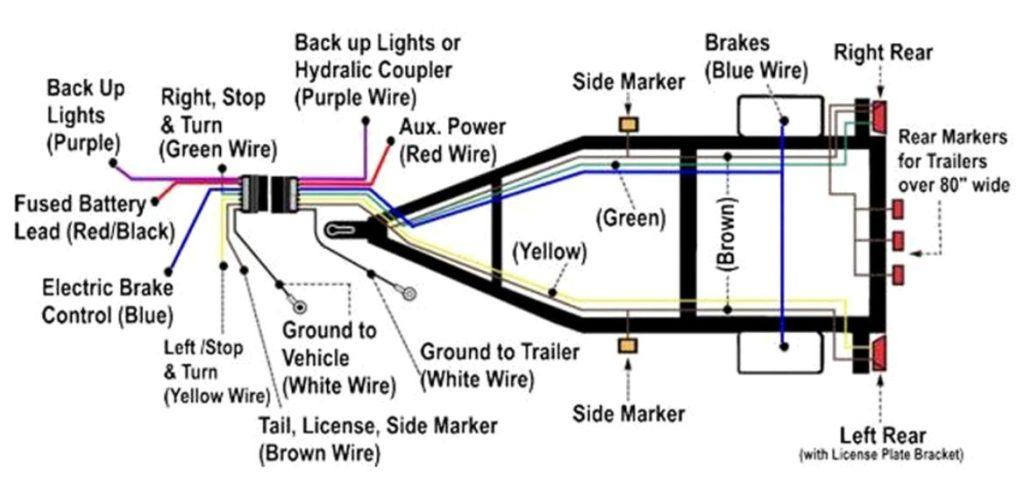
White Wire Notes
The white wire is the “Ground” or “Negative” wire, which runs from the vehicle’s battery to the “minus” terminal. According to the trailer’s wiring schematic, this wire powers the trailer’s lights and activates the electric trailer brakes.
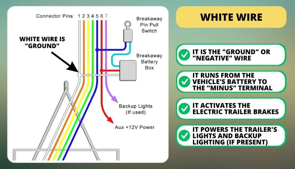
It should also be capable of linking up with accessories that require auxiliary power and backup lighting (if present).
Issues
Many trailer wiring diagram manufacturers connect this wire to the trailer’s frame. Where it connects with the ground from the rest of the trailer’s lights and components.
Yet, trailer wiring diagram electrical problems are frequently caused by issues with the grounding component of the circuit.
The white wire should also be directly attached to the trailer’s chassis.
Size
It is important to ensure that the white wire used for grounding is of the appropriate gauge, which should be as large as the biggest wire in your harness.
While a thin white wire may be sufficient for circuits with only low-power LED bulbs, a higher gauge wire is necessary for circuits that require electric brakes or auxiliary power.
Brown Wire Notes
The Brown Wire in the trailer wiring is responsible for connecting to the always-active lights along the trailer’s route. These lights typically include the high-intensity sections of the brake light, taillights, side and corner markers.

If the trailer wiring diagram has pairs of three lights located in the middle of the front and back, the Brown Wire is also responsible for connecting them. It is important to ensure that your trailer wiring lights meet the legal requirements of your area.
Not a DIY
These lights are not typically found on modest DIY utility trailer but may be required in other setups. If you desire these lights, the Brown Wire can supply power to them (along with the White Wire for grounding).
As always, it is important to verify your state and regional building codes to ensure compliance with the minimum lighting requirements.
Size
The Brown wire is solely used for powering lights, and thus its size should be appropriate. Since lighting typically does not consume a lot of power, a smaller gauge wire is sufficient for a utility trailer.
If you plan to install multiple running lights on a large enclosed trailer, it is recommended to use a larger gauge wire.
Yellow and Green Wire Notes
It’s important to make sure that the correct wires are connected to the correct lights to ensure that the trailer lights function properly and comply with local regulations.
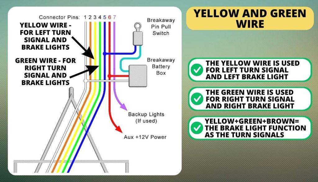
The yellow wire is used for:
- Left turn signal
- Left brake light.
The green wire is used for:
- Right turn signal
- Right brake light.
In some cases, the brake light may also function as the turn signals, in which case the yellow and green wires are combined with the brown wire to create a three-wire system.
Size
Using 16 gauge or larger wires for trailer wiring lights is recommended due to their superior strength, durability, and applicability.
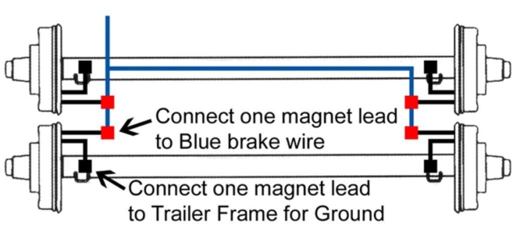
Blue Wire Notes
While the blue wire is usually associated with the electronic trailer brakes, its use is not as universal as that of the other two (lights and ground).
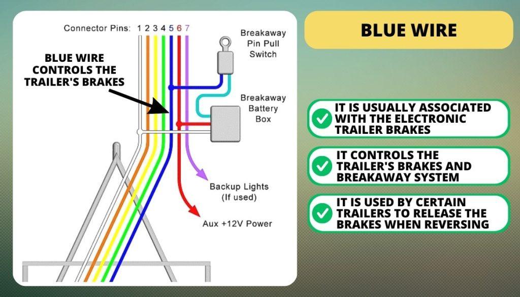
When a vehicle is equipped with electric brakes, the blue wire is sent to the brake controller. There are a variety of brake controller designs from which to choose; select the one that is compatible with your car. The blue wire controls the trailer’s brakes and breakaway system.
These are some other applications we’ve seen for the blue wire.
- This fifth pin is used by certain trailers with surge hydraulic brakes to release the brakes when reversing.
- If you want to do this, you must link the blue wire to the tow vehicle reverse lights.
- It would be preferable if you replaced the current wire with a purple one and clearly labeled it.
- The fifth connector is sometimes designated as “Reverse Lights.” If you do, make a note of it on the trailer, because a mistaken connection might result in a lot of headaches.
If you must use a 5-pin connection, do so with extreme caution. Check the trailer’s wiring to make sure it corresponds to the car’s needs.
Tow Vehicle Incompatibility
For situations when the tow vehicle wiring is incompatible with the trailer’s. Such as when a buddy wants to borrow it, have a small adapter that converts the trailer’s 5-pin harness to a 4-pin vehicle, allowing it to be towed without using the brake controller.
The trailer’s small size and light weight make this possible, as they are not needed while carrying a relatively little load. Even though the actual load capacity is 5000#, I only inform the borrower that it can support 3000#.
Alternate Option
A different option is to use an adaptor to convert the 7-pin connector found on most vehicles to the 5-pin connector found on a trailer wiring diagram (with 2 wires left blank). In this method, the trailer’s brakes will be prepped if the tow vehicle uses a 7-pin hookup.
Size
To ensure your brakes function properly, it is essential not to compromise on wire size. For a single axle, a 14-gauge wire is adequate, but for tandem axles, it is recommended to use a 12-gauge wire.
Red Wire Notes
The Aux Power pin is typically identified by a red wire, although other colors may be used as well. This power source, also known as auxiliary power, accessory power, or batt 12V+, carries a positive DC from the tow vehicle.
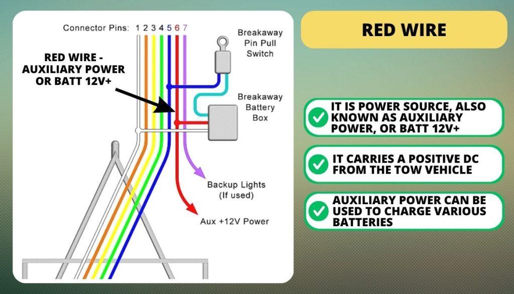
Auxiliary power can be used to charge various batteries, including vehicle batteries, RV batteries, interior light batteries, accessory batteries, and more.
What to Avoid?
If you don’t want to use the trailer’s power source, you can leave the pin out. However, if you decide to utilize it, it is important to protect the car’s electrical system from any potential shorts by using a fuse or circuit breaker. Avoid completely discharging the tow vehicle battery is also advisable.
Size
The appropriate cable size should be selected based on the power demand. For powering the breakout battery charger, a 16-gauge wire is sufficient.
However, if you intend to charge additional batteries or operate trailer lighting, it is recommended to switch to a 14 or even a 12-gauge wire. It is important to avoid overloading this wire to prevent any electrical issues.
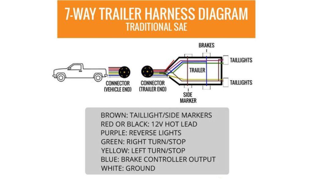
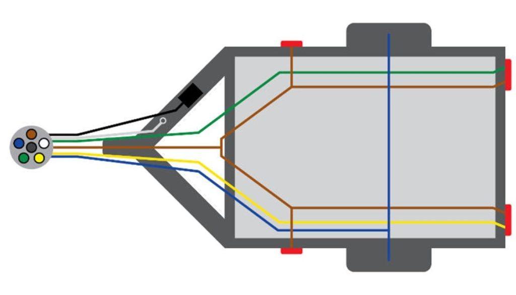
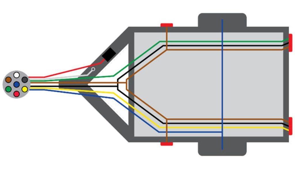
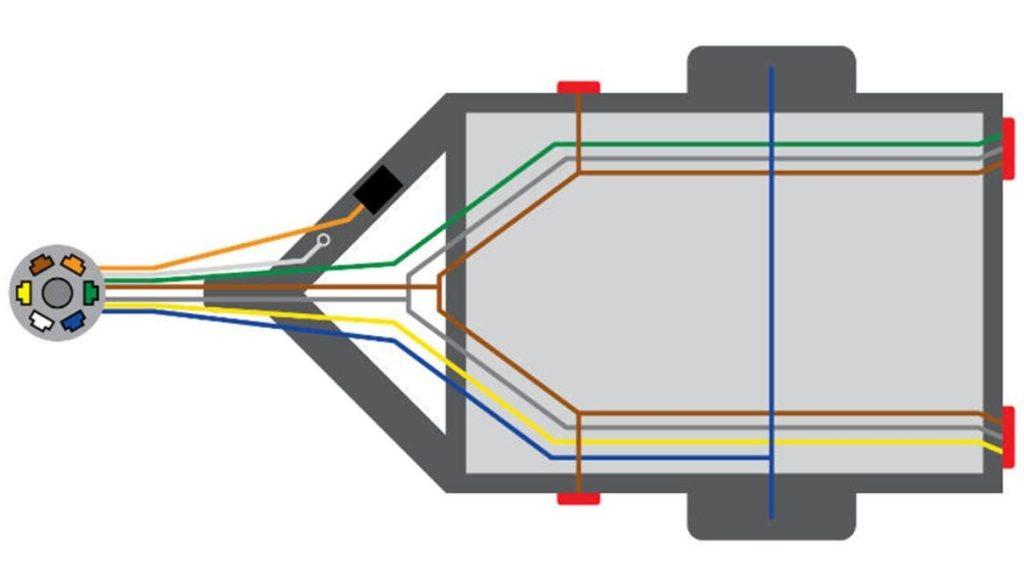
Wire Routing Notes
There is one possible wiring path for a trailer, which involves routing the wire from the tongue connector around the entire trailer. In contrast, others advocate for splitting the wires with separate paths for the right and left sides. Neither is superior to the other.
Although we believe that the wrap-around method provides a more efficient trunk for power distribution. Additionally, the wires are secured as they pass through the tongue.
Comparison: 6 Pin Trailer Plug Vs 7 Pin
Several situations are better served by the 6-pin design. But, we have discovered that it is possible that not all of your trailer’s features, lights, etc., will function. The trailer’s backup lighting will activate when the tow vehicle is put into reverse, thanks to the seventh pin on the 7-pin model.
- The yellow wire is often connected to the center pin.
- The AUX pin can supply power to anything else. It’s usually the trailer’s reverse lights.
- You can omit it if your state does not mandate that trailers have backup lighting.
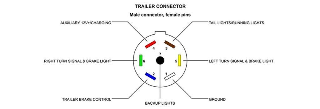
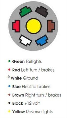
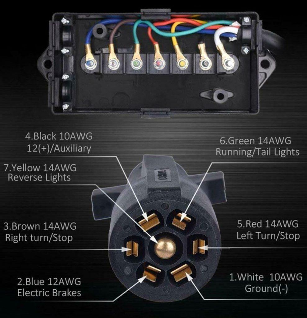
Black Wire (Center Terminal) on a 7-Pin Trailer Plug
The way the 7-pin is marked is as follows:
- 1 White = Ground
- 2 Blue = Brake
- 3 Green = Running Lights
- 4 Black = 12v+
- 5 Red = Left Turn
- 6 Brown = Right Turn
The 7th isn’t marked but is the center terminal.
6 Pin To 7 Pin Trailer Adapter Wiring Diagram
Here is a wiring diagram for a 6-pin to 7-pin trailer adapter:
6-Pin | 7-Pin | ||
Color: | Function: | Color: | Function: |
White | Ground | White | Ground |
Brown | Tail | Blue | Brake |
Yellow | Left turn | Green | Tail/running lights |
Green | Right turn | Brown | Backup lighting |
Blue Wire (or red) | Brake | Yellow (or red) | Left turn/brake |
Red | 12V+ | Red (or blue wire) | Right turn/brake |
N/A | N/A | Black | 12V+ |
This wiring diagram shows that the 6-pin trailer connector includes six wires, while the 7-pin trailer connector has seven. Each wire has a specific function as outlined below:
- Pin 1 is connected to a white ground wire and functions as the ground wire.
- Pin 2 is connected to a brown wire and is responsible for powering the tail lights.
- Pin 3 is connected to a yellow wire and activates the left turn signal.
- Pin 4 is connected to a green wire and activates the right turn signal.
- Pin 5 is connected to either a blue or red wire and is used for the brake light.
- Pin 6 is connected to a red wire and provides 12V+ power.
- Pin 7 is connected to a black wire and is also used for 12V+ power.
To construct the adapter, it is necessary to match each wire on the 6-pin connector to its corresponding wire on the 7-pin connector, as indicated in the table above.
It is important to follow the correct color code for each wire to ensure the proper functioning of the trailer wiring diagram.
Refer to the video here for a better approach.
Safety Measures For Protecting Wires For a 7-Pin Setup
If you need to run cables for a considerable distance, here are some safety precautions you may take.
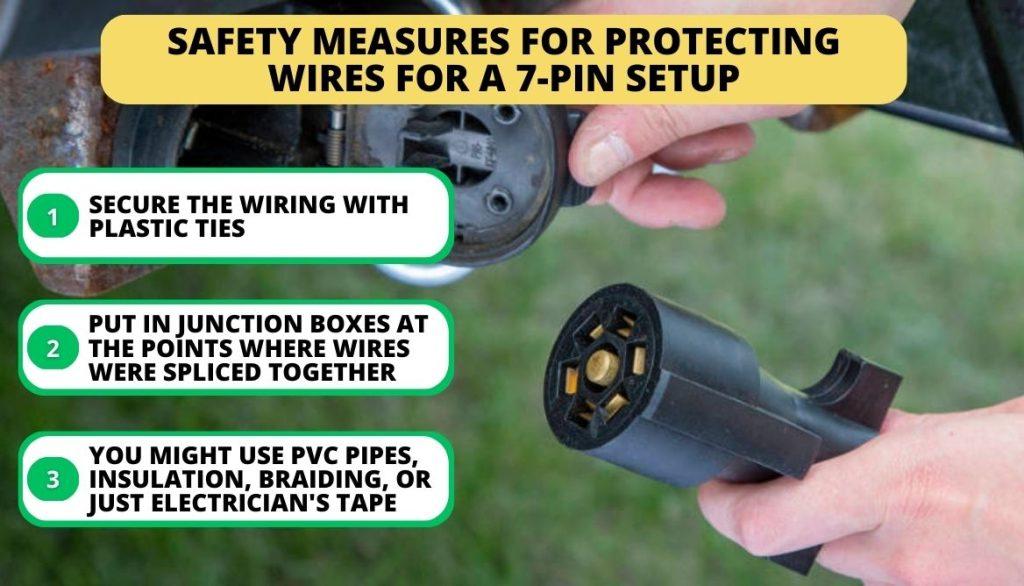
- Secure the wiring by tying it to the trailer’s frame. The best option would be to use some plastic ties.
- Protect the wires from damage by running them through plastic or other non-metallic conduits. Put in junction boxes at the points where wires were spliced together.
- Instead, you might use PVC pipes, insulation, braiding, or just standard electrician’s tape. Hangers and clips made of wire will also do the trick.
6-Pole Trailer Wiring Diagram
6-Pole Trailer Wiring Diagram
6-Way Vehicle Diagram

7-Way Vehicle Diagram

7-Way Vehicle Diagram
6-Way Flat Connector Diagram

6-Way Trailer Wiring Color Code

6-Way Trailer Harness Diagram

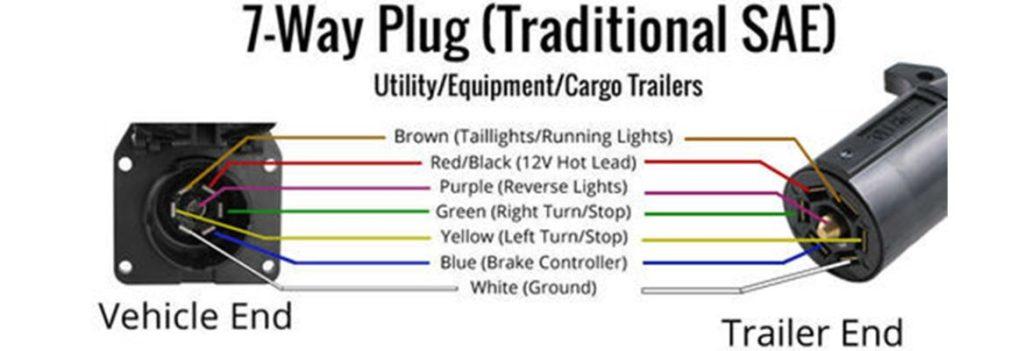
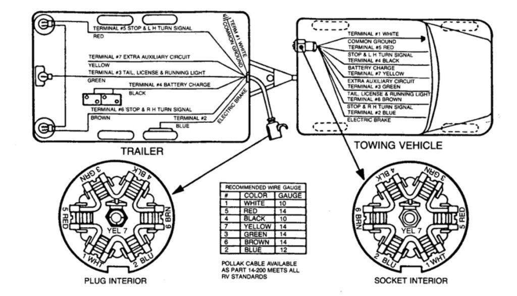
7-Way Flat SAE Connector Diagram
7-Way Plug RV Standart Diagram

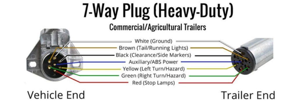
7-Way Plug (Heavy-Duty)
7-Way Trailer Wiring Color Code Traditional SAE
7-Way Trailer Harness Diagram – Traditional SAE
7-Way Trailer Wiring Color Code RV Standart
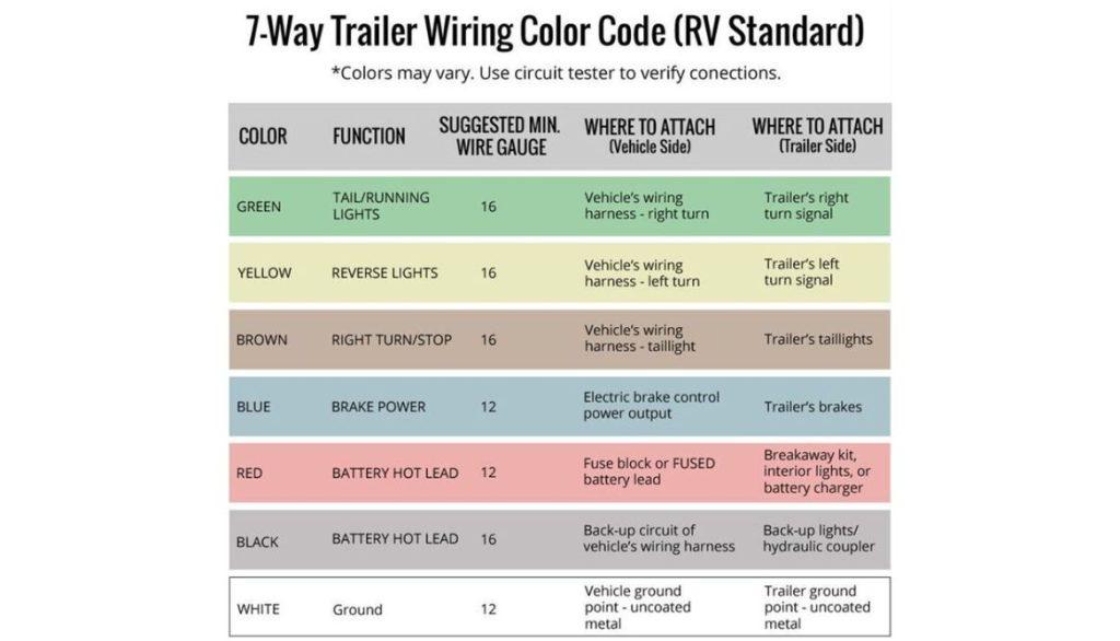
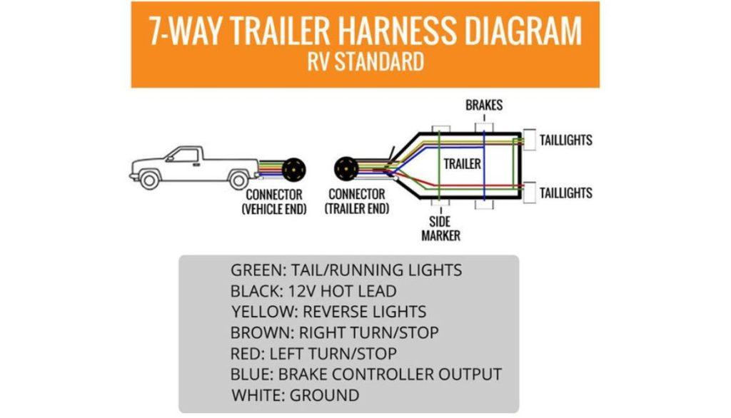
7-Way Trailer Harness Diagram – RV Standart
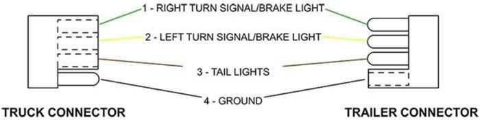
Typical 6 Pin Truck Connector Pinout Diagram
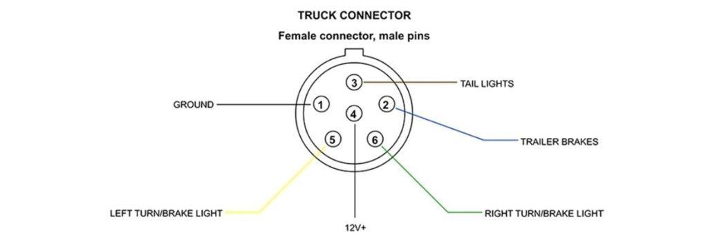
Typical 6 Pin Trailer Connector Pinout Diagram

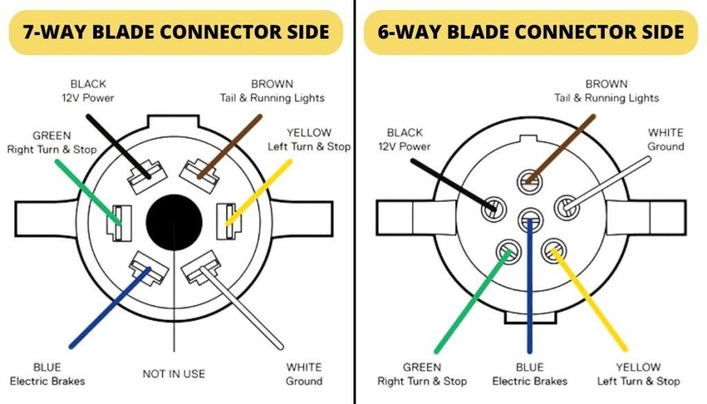
Typical 7 Pin Blade Type Truck Connector Pinout Diagram
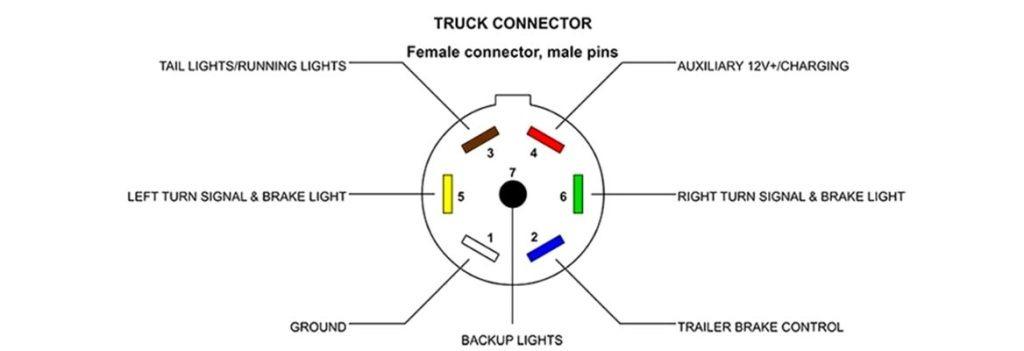
Typical 7 Pin Blade Type Trailer Connector Pinout Diagram
7-Way RV Style Trailer Plug Wiring

6-Pin Trailer Wiring Diagram
6-Way Round Trailer Wiring Color Code

6-Way Square Trailer Wiring Color Code

Round 7-Pin Wiring Diagram
7-Way Round Trailer Wiring Color Code
RV Blade 7-Pin Trailer Wiring Diagram – SAE
7-Way RV Blade – SAE J2863 Trailer Wiring Color Code
RV Blade 7-Pin Trailer Wiring Diagram – Traditional

7-Way RV Blade – Traditional Trailer Wiring Color Code
7 PIN SMALL ROUND TRAILER PLUG WIRING DIAGRAM
7 PIN SMALL ROUND TRAILER SOCKET WIRING DIAGRAM

7 PIN FLAT TRAILER PLUG WIRING DIAGRAM

7 PIN FLAT TRAILER SOCKET WIRING DIAGRAM
7 PIN LARGE ROUND TRAILER PLUG WIRING DIAGRAM

7 PIN LARGE ROUND TRAILER SOCKET WIRING DIAGRAM

7 Wire Trailer Circuit Wiring Diagram
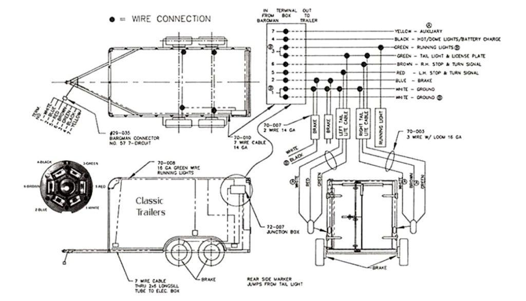
7-Way Cord Diagram
7-Wire Trailer Wiring

7-Way Connector Wiring/Function Diagram

7 Way Plug Inline Trailer Cord
FAQ
What is the most common trailer wiring?
The most common is the 7-way connector trailer wiring as it has backup lighting in addition to everything else in modern SUVs, trucks, and recreational vehicles.
Can you use a 7-way plug with 6 wires?
Yes, you can use a 7-way plug with 6 wires! A 7-way trailer connection may be easily added to a trailer with only 6 wires.
What is a 6-pin trailer connector?
A 6-way trailer connector has one wire for trailer brakes and one wire for a battery hookup in addition to the standard running lights, brake light, turn signals, and ground wire.
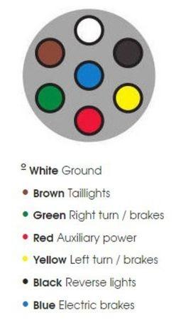
What are the wires in a 7-pin trailer wiring harness?
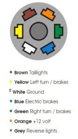
7 pin trailer wiring harness has a white ground wire, brown for taillights, green for right turn/brakes, red for auxiliary power, yellow for left turn/brakes, black for reverse lights, and blue wire for electric brakes.
What is the color code for the 7-pin trailer wiring?
The color code for 7 pin trailer is the following: a green light indicates a right turn. When you see a yellow light, you should turn left. The backlights on a trailer are brown, whereas the ground is white.
Conclusion
Finding the appropriate adaptor is essential for joining a 6-pin trailer connector to a 7-pin plug. Nevertheless, 7-pin devices contain both flat and round pins, whereas 6-pin models exclusively have round pins, so you’ll want to be careful.
Assuming you follow the proper procedures make this connection risk-free. Have you ever made such a connection before? Did the 6-pin to 7-pin trailer wiring diagram prove helpful to you? Let us know your valuable answers in the comment section below!

I`m a current Law Enforcement Officer working within the Counterterrorism Bureau in New York State. I have been Camping for over 20 years. My styles of camping include tent, car, truck, van, and RV travel trailer. I have a YouTube channel where I teach all types of camping with an entertaining method: https://youtube.com/@TheSmallsRVAdventures


