50 Amp 3 Prong Plug Wiring Diagram: What You Need To Connect This?
By following the 50 Amp 3 Prong Plug Wiring Diagram, we can make safe and reliable electrical connections. Pay attention, that without a proper wiring diagram, there is a risk of electrical shock, fire, and damage to equipment.
Read on to learn about 6 new wiring schematic instructions, 3 RV distribution panel recommendations, and the components you need to link a 50 amp plug for a smooth wiring process.
Let’s get started!
Table of Contents
50 Amp Plug Wiring Schematic Must-Follow Instructions
There are numerous examples available that can serve as a guide for creating your wiring diagram. It’s important to choose the appropriate diagram that matches your needs and follow its instructions precisely.
While installing new 50-amp RVF plugs is a simple task, switching off the electricity is essential before you begin as a safety precaution.
Hot Wires and Bare Ground Wire
Let’s learn how wiring color works:
| Wire | Color |
| Hot Wire | Red/Black |
| Neutral | White |
| Grounded Wire | Bare/Green |
In case, the diagram you are using is unclear, get help from the color codes mentioned above. Please note that your RV’s “hot” and “ground” wires may have different colors. Read the user’s manual in that case.
50 amp 3 prong Plug Wiring Diagram: Instructions for Making Connection
Here are a few steps regarding the wiring schematic for a 50-amp RV plug:
- Power: Switch off the main power supply.
- Color Codes: Understand color coding. You can see the table mentioned above for a better understanding.
- Strip Insulation: Identify the correct terminals on the plug, strip the insulation off the wires, and connect them. The brass terminals are designated for the main or hot wires, while the silver terminal is intended for the neutral wire, and the green terminal is used for the grounded wire.
- Connection: Tighten the terminal screws securely to ensure that there are no loose connections.
- Outlet Box: Screw the plug into the outlet box once you have connected all the wires.
- Checking: Turn the power back on and test the connection with a voltage tester to ensure proper operation.
Power Associated with 50 Amp RV 4 Prong Plug Wiring Diagram
For the most part, wiring this plug is similar to wiring the plugs discussed in the previous section:
- The two hot wires must be connected to the right prongs, while the other two prongs should be used for the neutral and ground connections.
- Once you understand how everything fits together, wiring the plug should not take much time.
- However, it is important to turn off the power when working with wires or connections.
- 50 amps – 240 volts.
- 30 amps – 120 volts.
50 Amp RV Distribution Panel Wiring Diagram
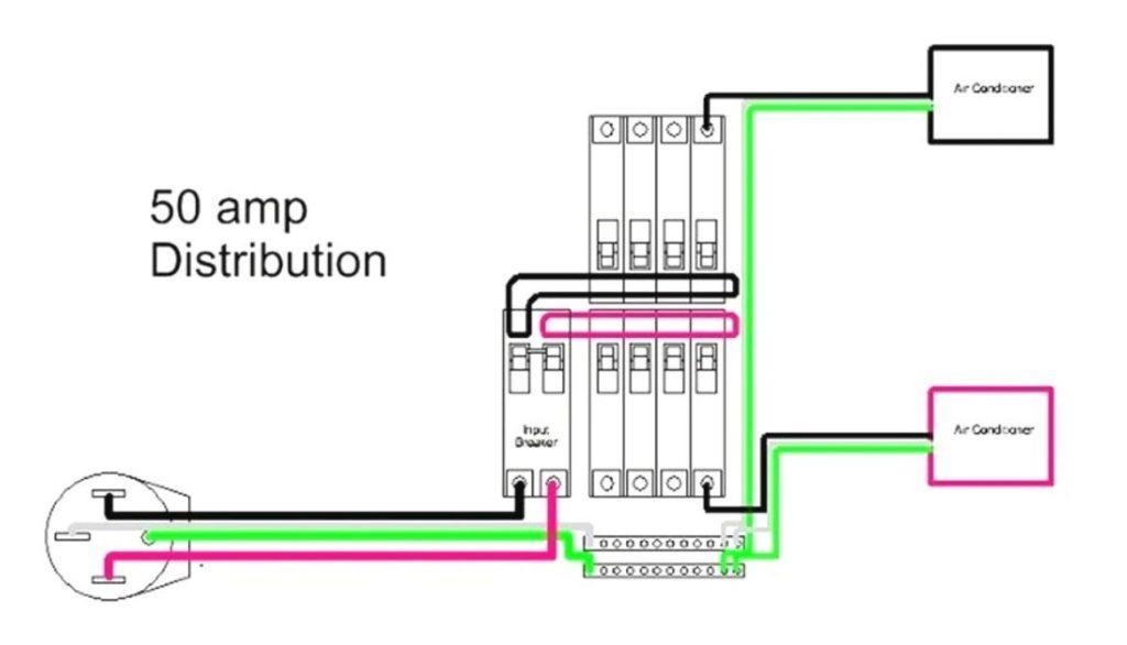
To ensure that this task is performed correctly, it’s important to keep the following recommendations in mind:
- Check Connections: If the connections appear to be secure, it’s easy to assume that they are tight. However, it’s essential to check them thoroughly, especially when you are using a 50-amp outlet because inappropriate wiring can lead to disastrous consequences.
- Use Multimeter: After completing the connections, use a multimeter to check for power. If the system is not registering at all or is registering poorly, an error was likely made in the process, and you should review it carefully to identify the mistake.
- Follow Guidelines: Always follow the guidelines established by the National Electrical Code to ensure that your wiring system is both functional and safe. Obtain a copy of the code or the relevant section that resembles your project, and adhere to it strictly.
Following these recommendations are crucial for your safety and to minimize the hazards posed by improperly connected electrical components.
See this video for further clarification.
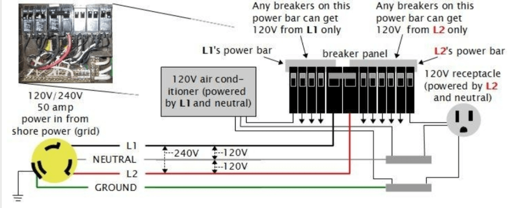
50 Amp Plug RV Breaker Wiring Diagram
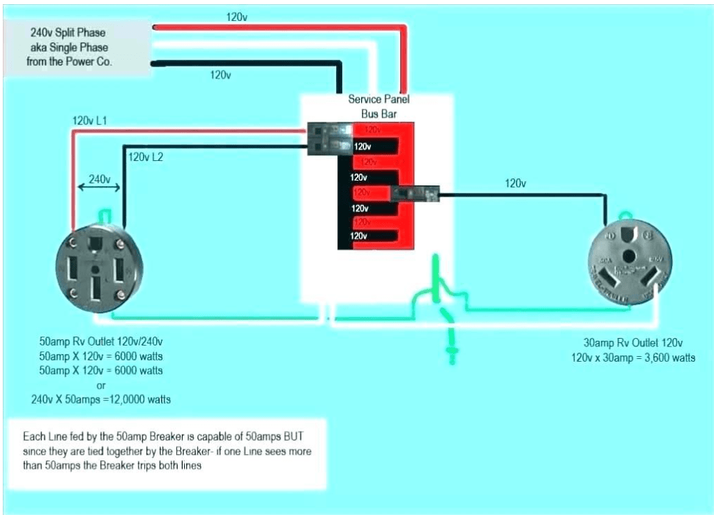
Most 50 Amp RV breaker wiring diagrams include an electrical circuit breaker box, a 50 Amp RV receptacle, and a 50 Amp RV circuit breaker for 240 Volt.
The circuit breaker is hardwired to 2 hot wires, an unbiased wire, and a grounded wire in the main electrical breaker panel. The red and black wires are the hot ones, one is white neutral, and the green one is ground.
To speed up your wiring process, carefully link:
- Hot wire to the breaker’s two terminals
- Unbiased wire to the electrical panel’s neutral bar.
- Grounded wire to the panel’s ground bar.
- 50 Amp RV receptacle with red wire and then to hot prong.
- Black wire to the other hot prong.
- White wire to the neutral prong.
- Green wire to the ground prong.
It’s crucial to check the wiring and make sure everything is linked properly and securely to prevent any accidents.
For more details check out this video.
What do You Need to Connect a 50-Amp Plug?
Connecting a 50-amp plug requires a few basic components, including:
- 50-amp breaker
- RV outlet
- Electrical conduit
- A wire (preferably 6/3 gauge, but 8 gauge can suffice in an emergency).
- Plugs
However, a plug can be installed on the exterior of a building or garage or mounted on a pedestal, similar to the ones found in campgrounds.
Here are the few essential components that you will be needing:
1. You Need a Breaker
To divide a 240-volt service into two 120-volt hot feeds, you will require a 50-amp double or dual-pole circuit breaker designed for 120 volts. The dual breaker consists of two separate breakers that are bridged together, and some circuit breakers come with a built-in bridge.
2. The Electrical Wire Needed
The recommended wiring usage for an RV receptacle typically includes the following:
- 8 gauge for 25 feet or less
- 6 gauge for 25-50 feet
- 4 gauge for 50-100 feet
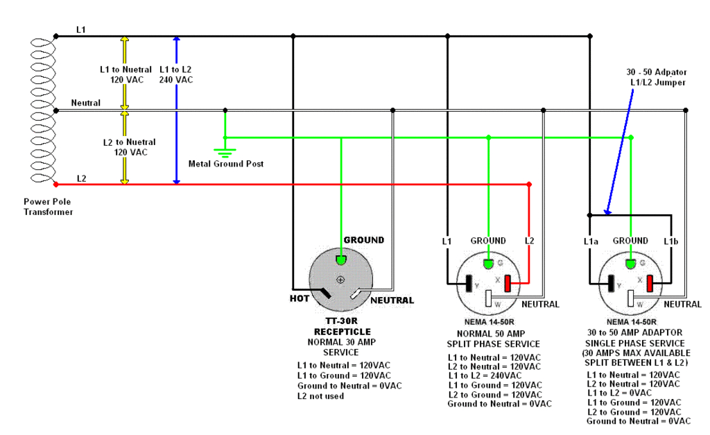
3. Outlet Types
If you connect an RV receptacle to a standard 15-amp or 20-amp outlet, the amount of electricity you can utilize is restricted. Most recreational vehicles require either a 30-amp or 50-amp connection, with both performing at their best with the appropriate amount of electricity.
A popular misconception is that utilizing an adapter to connect a 30-amp to a 50-amp system outlet will provide increased power access, however, this is not true. The appliance will only be able to charge using 30 amps of power.
On the other hand, if 50-amps system is linked to a 30-amp outlet, only 30 amps of power will be available, which equals 3,600 watts in the United States (assuming a 120-volt system).
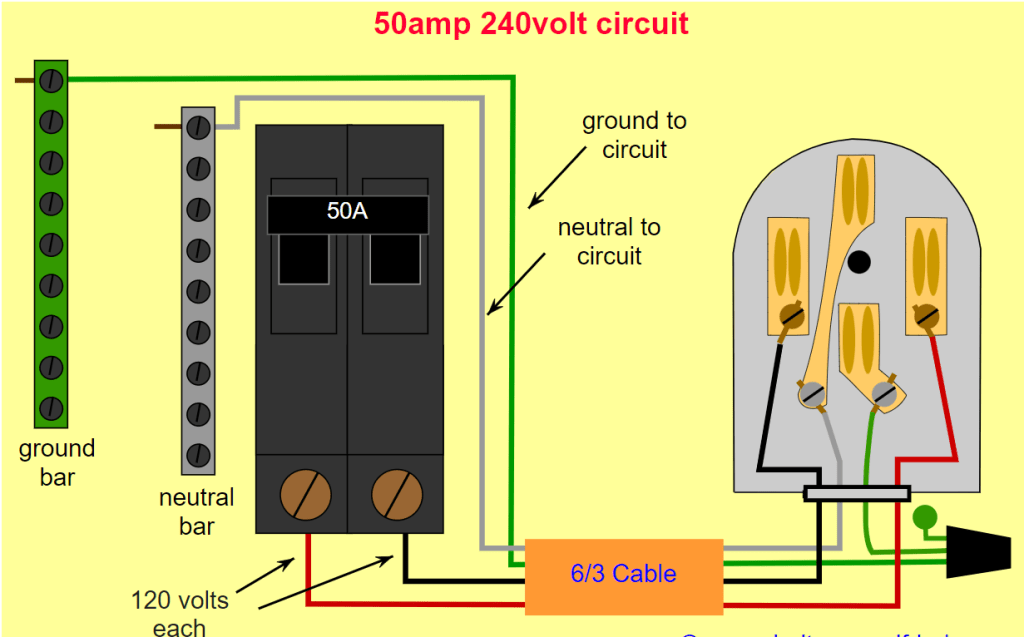
Wiring Your 50-Amp RV Outlet Step-by-Step
It is not difficult to wire this sort of outlet. The rear of your receptacle will have four terminals or screws (often color-coded):
- For grounded wire use a green terminal
- For HOT wires use (2) brass terminals
- For the unbiased wire use a silver terminal
Here is the process for effective wiring:
- Step 1 – Preparation: Prepare the necessary wiring by gathering your supplies. A weatherproof enclosure, 50-amps outlet, and a wire (6 gauge) are all you need. Get your tools ready for installation, too.
- Step 2 – Safety First: Turn off the main power source
- Step 3 – Locate a Place: Your circuit breaker box may require an expansion added if there are no free spaces.
- Step 4 – Running Your Wires: Before you attach any of the sides, you should feed the wires through the conduit.
- Step 5 – Connecting Outlet: To wire the side slots of your outlet, you should use a red and black (or black and black) cable, which may be color-coded as brass. The U-shaped end with a bare/green wire, should be used along with the white/neutral wire at the bottom.
- Step 6 – Linking the Breaker: The circuit breaker is wired with either two black wires or a combination of black and red wires.
- Step 7 – Linking to Bus-Bars: The ground and neutral buses in your electrical main breaker box are the terminal blocks with all the little holes. At this hole, you may insert the necessary cables and secure them with a screw. The neutral bus is where the white wire goes, while the ground bus is where the bare (or green) wire goes.
- Step 8 – Turn the Power Back ON: Restart the machine and the lights will come on. Even if you’re positive that you’ve done everything well, you should still use a surge protector or double-check it with a multimeter.
Here is a diagram for assistance:
Testing Your Outlet
As said, you shouldn’t trust just anyone when it comes to testing an RV plug (including a professional that installs it). You may be the one to shoulder the costs of someone else’s carelessness.
Also, you can no longer afford to be lazy now because checking the outlet is so simple. Testing for proper voltage may be done with a multimeter (or voltmeter), or you can just plug in a surge protector and look for the green light to come on.
If using a multimeter (or voltmeter) the voltage between:
- Hot wires should be = 240 volt
- Ground and Hot = 120 volts
- Ground and Neutral = 0 volts
- Neutral and Hot = 120 volts
Using Your Outlet
Every plug has the potential to extract a significant amount of power! With the 50-amps service, you can link a greater number of appliances compared to the 30-amp service.
However, it’s important not to overlook certain guidelines that are typically included in all RV manuals when in a rush to begin your journey.
Below are the steps to correctly connect your RV to shore power, whether you’re parked at an RV site or at home:
- Turn Off All the Appliances: To begin, never link your cord while it is being used.
- Turn Off Shore Power or RV Breaker: That way, you won’t have to worry about getting a shock or having a lightbulb flash on by accident.
- Plugin Your Cord: Make sure the prongs on the plug match up with the prongs on the socket.
- Turn on the Breaker: The RV or shore power breakers can be turned ON once the plug has made contact and is securely positioned in the socket.
Common Mistakes and How to Avoid Them?
Many common errors may be made when wiring a 50-Amp schematic. Some of these errors and suggestions for avoiding them follow.
| Mistake | Solutions |
| 1. Using incorrect wire size | Use the appropriate gauge of wire for the circuit. Check the NEC to see what size wire you need for your circuit breaker box. |
| 2. Installing a shared circuit instead of a dedicated one | A 50-Amp circuit needs its power source and shouldn’t be shared with other devices. |
| 3. Failure to utilize a breaker with a sufficient amperage rating | Use a circuit breaker with the correct nominal current to avoid overheating. |
| 4. Not properly grounding the circuit | Make sure the circuit is correctly grounded by turning the multimeter to the highest AC voltage range available and checking the measurement. |
| 5. Defying electrical safety regulations | Be sure to always follow local electrical codes. |
While wiring a 50-Amp schematic it’s important to adhere to all applicable regulations and guidelines.
FAQ
What color wire goes where on a 3-prong plug?
Modern home electrical circuits that use 120-volt power typically have three wires with different colors. These wires are a “hot” wire, which can be either black or red in color, a “neutral” wire, which is always white, and a “ground” wire, which is always green or bare.
Why does a 50 amp plug have 4 prongs?
50 amp plugs have 4 prongs because RVs require a special prong plug that can handle high amps. One of the four wires in the power cable is linked to each of the prongs. Each of the two prongs is capable of carrying 50 amps of electricity at 120 volts AC.
How do you wire a 3-pin plug correctly?
We can wire a 3-pin plug correctly by attaching the flex to the plug. Then, connect the green/yellow wire to the earth terminal (E), the blue wire to the neutral terminal (N), and the brown wire to the live terminal (L).
Which is positive and negative on the 3 prongs plug?
The positive terminal is the red wire. There is a negative charge on the black wire. If there were a grounded wire, it would be white (sometimes called neutral in DC).
Conclusion
We hope with the above-mentioned recommendations, and the 50 Amp 3 Prong Plug Wiring Diagram, you will be able to carry out the task without any assistance. Always take precautions to ensure the safety of your loved ones and property.
Were you familiar with the uses of neutral wire, ground wire, and hot wire before? Do you always check the maximum amperage rating when connecting the plug? Let us know your answers in the comment section below as we will love your feedback!

I`m a current Law Enforcement Officer working within the Counterterrorism Bureau in New York State. I have been Camping for over 20 years. My styles of camping include tent, car, truck, van, and RV travel trailer. I have a YouTube channel where I teach all types of camping with an entertaining method: https://youtube.com/@TheSmallsRVAdventures


