
Looking for a reliable Goodman furnace thermostat wiring diagram? Installing thermostats or wiring the different components can be a challenging and technical task. But, you can easily follow step-by-step color coding on a diagram to achieve the results.
In this article, we will give Goodman furnace thermostat wiring diagram, discuss colored wiring, letters that identify those wires as a code, and the placement of the wire on the thermostat panel. Let’s get started!
Goodman Furnace Thermostat Wiring Diagram: How It Looks Like?
The Goodman furnace thermostat wiring diagram may look complicated at first, but with a little research and understanding it is easy to understand. For a much simple demonstration, refer to the diagram below:

What do ADPF, ARPF, ARUF, and ATUF Stand for in Goodman Thermostat?
Air handlers made by Goodman have different models labeled ADPF, ARPF, ARUF, and ATUF. Such air handlers are used in Goodman furnaces for efficient heating and cooling for your home or a larger space.
[wptb id=3010528]They are best known as multi-position air handlers with a variable-speed motor that is designed and installed in a configuration of downflow, up flow, left, or right.

3 Methods to Wire Goodman Thermostat
The configuration to wire the thermostat may vary. And there are 3 different methods to do it. Below are the details on how to do the wiring. Read on!
Method 01: Replace the Thermostat’s Wire One by One
If you are changing the HVAC components, adding a new wire, and installing a new thermostat. Here is how you do it!
- Make sure to switch off the electrical circuit to the air handler or furnace.
- Take a picture of the existing wiring on the terminals. This will help in scenarios if you forget the sequence of the wiring.
- Another trick is to label all the wires with tape and write the terminal code on each of them.
- Start to detach the wire from the original thermostat and connect it to the same coded terminal on the new thermostat.
- Remove one wire at a time so that there is no confusion while shifting all of them.
- Now, restore the power to the thermostat and adjust the settings for heating or cooling.
If you have done everything perfectly then it will work for sure. But, if it doesn’t then consulting a local HVAC company is the best approach.

Note: If it is possible that all wires may not be used while changing the wiring. If there are any wires left then simply twist them and tape them to avoid any electrical mishaps via bare wire touching the internal bare components. You will not need a new wire.
Method 02: Locate the Wiring Connections in the Furnace or Air Handler
You may have a much more complicated task at hand if the thermostat has already been detached. A never of methods may work. Try the one mentioned below!
- Cut off the power supply for the gas furnace or air handler first.
- You need to guarantee that the system is off by changing the call for heating or cooling settings. If the system does not respond then carry on with your work.
- Locate the cover of the furnace or air handler and remove the terminal screws to uncover it.
- Locate the thermostat by identifying the wire bundle that enters the furnace. If the bundle you find has 3 to 8 different colored wires then you have located the right wires.
- Red, white, green, yellow, orange, blue, and black are the coloring you are looking for.
- It may be required to take off the cover above the control board to reach the wiring connections inside.
- After you have located the wiring connection terminals. Take a picture of the existing setup for future reference.
- On the furnace or air handler each wire has a code that needs to be connected with the right type of wire. Do not cover the furnace until you get all the wires connected.
- Take a look at the photo or if you have noted down the coding/colors of the wire. Use it to link the colored wire to the correct terminal on the thermostat.
- Resume the power supply to the circuit and adjust the call for heating or cooling on the thermostat.
Note: As mentioned before, not all wires may be used while changing the thermostat. This is not something to worry about.
If you have connected everything perfectly then it will work fine. Once you have confirmed that it is working fine then cover the back of the furnace. If it still does not work properly, contact an expert HVAC technician for help.
Method 03: Using Standard Wiring Colors to Connect the Thermostat
If the thermostat has been detached and you have no idea where to attach the colored wires or you cannot understand the codings. This method will work for you to properly wire your thermostat using the traditional wiring color code.
Note: The colors on the wire do not mean that their material is different (e.g. made of something else instead of copper). The color coding is only to make it easier to identify and remember the wires.
Here is how you do it using a wire drawing, check out the table below!
[wptb id=3010531]Use the help of the table below if you are switching from Goodman’s old thermostat to a newer one.
[wptb id=3010534]*”O/B” is used if your system is a Heat Pump.
Note: Twist the ends and tape the ends of any additional unused wires to avoid any electrical accidents later.
Thermostat Wiring Color Codes
Each wire is denoted with a color and the color identifies the purpose of the wire. Here is a list of the different wires and their details!
1. Black, Common, And Blue Thermostat Wire (C Wire)
Let’s shed some light on the purpose of the Blue thermostat wire:
[su_list icon=”icon: check” icon_color=”#00cf77″]
- The blue wire is given the purpose of the Common or C-wire, also it can be in Black.
- It is associated with the transformer and attaches to the 24V electric circuit.
- In the older models, this black or blue wire is not found as they function on a need-based.
- In the newer models such as the smart thermostats, they are present because they need 24/7 functionality.
[/su_list]
2. Red Thermostat Wire (“R” or “Rc” Wire)
For a heat pump, the assigned wire is the red thermostat wire. Let’s learn more about it:
[su_list icon=”icon: check” icon_color=”#00cf77″]
- Commonly purposed as the “R” wire or better known as the power wire.
- Its purpose is to channel electricity to the transformer around the clock.
- It is located at the air handler in airconditioners.
- All models of ACs have this wire but you will sometimes come across Rc or Rh terminals, especially when dealing with dual transformer systems.
- These are exceptional scenarios when working on a thermostat.
[/su_list]
3. White Thermostat Wire (“W1” or “W2” Wire)
Let us tell you about the purpose of the white wire in a thermostat:
[su_list icon=”icon: check” icon_color=”#00cf77″]
- The wire responsible for heating (heat pump) is the white color wire.
- It is only present in furnace thermostats and not in cooling units such as air conditioners.
- The W2 wire has a special purpose, it is for two-stage heating (heat pump) and several heaters have this function. So, you commonly come across this wire while working on it.
[/su_list]
4. Orange Wire For O And Dark Blue Wire For B (“O/B” Wire)
What purpose does an orange-colored wire serve? Let’s check it out:
[su_list icon=”icon: check” icon_color=”#00cf77″]
- The “reversing valve” cooling is controlled by the orange thermostat wire or better known as the “O” wire.
- In a large-sized heat pump from brands such as Goodman, the orange wires run straight to the condenser that is present in the outdoor unit.
- Similarly, the reversing valve heating is controlled by a wire labeled “B”.
- It is color-coded as a darker shade of blue. This wire serves the purpose to connect to the t-stat terminal.
- In most major brands it is responsible for providing power to the reversing valve. It becomes active on initiation of the heating mode on heat pumps.
[/su_list]
5. Green Thermostat Wire (“G” Wire)
The function of green wire is:
[su_list icon=”icon: check” icon_color=”#00cf77″]
- The fan is powered or controlled by the “G” wire.
- The wire regulates the power that is channeled into the mini-splits.
- It consists of an indoor air handler and also comes with a fan.
[/su_list]
6. Yellow Thermostat Wire (“Y1” And “Y2” Wire)
The yellow colored wire controls the following:
[su_list icon=”icon: check” icon_color=”#00cf77″]
- Yellow thermostat wire or the “Y” terminals attaches to the compressor relay.
- Normally found connected with the air handler (indoor split AC). As the name suggests, the Y wire will usually be yellow colored.
- The Y1 is used for ordinary or single-stage cooling units found in many households.
- The Y2 is found in air conditioning integrated with second-stage cooling technology.
- You may need the Y2 if you have a unit with 2 compressors or a two-stage compressor.
[/su_list]
For more details, check out this amazing video!
7. Other Wires (BK, RS1, RS2, ODT1, ODT2, AUX NO, AUX C, AUX NC)
On the right side of the thermostat, some terminals are rarely used. Although, there may be plans for the brand to integrate any new features that might use these terminals.
Note: Color coding might be a little different in other brands of thermostats. The “O” wires are not always colored orange. If a technician has tweaked the settings then there is a possibility he might have changed the setting of the wires.
Common Thermostat Wiring Options – 2 Wire to 8 Wire Thermostats
There are different methods to wire the thermostats and depending on the model a certain setup might be best for it. Below are some wire configurations that may help you solve the technical difficulties. Learn more info!
Here is a super helpful video to get you started!
2 Wire Thermostat Wiring
There are several ways to set up the wiring when you are replacing the thermostat. It is crucial to know the various wire options for your heating or cooling system. The simplest and easiest are two-wire configurations. Let’s get started!

[su_list icon=”icon: chevron-circle-right” icon_color=”#00cf77″]
- Wires Needed: Red and White
- Where it is found: Hot water heaters (heat pump), AC units
[/su_list]
How to wire a 2-wire Thermostat
[su_list icon=”icon: chevron-circle-right” icon_color=”#00cf77″]
- Attach R to Power Source: The red wire needs to be attached to the R terminal to supply 24V power to the circuit.[/su_list]
Note: There is an RC terminal (old thermostat) then the red wire needs to be connected to it.
[su_list icon=”icon: chevron-circle-right” icon_color=”#00cf77″]
- Attach White wire to W: You need to attach the white wire to the W terminal responsible for heating (heat pump).[/su_list]
Reminder: There is no C wire in furnace-only setups. So, a common (C wire) is not required eliminating any possible c wire issue.
[su_list icon=”icon: chevron-circle-right” icon_color=”#00cf77″]
- Cover with Wires: Tape the ends of any unused wires after twisting the ends and the two-wires configuration is complete.[/su_list]
3 Wire Thermostat Wiring
There are slight complications with this setup of wires as it consists of a common or C wire. Many modern thermostat owners have expressed three-wires to be challenging.
Although we are explaining the process in a precise and easy way if there is any confusion then it is better to consult an expert. Read along!

[su_list icon=”icon: chevron-circle-right” icon_color=”#00cf77″]
- Wires required: Red, white, C wire with green or black
- Where it is found: Goodman Heating only system, most boilers, or water heaters have a 3-wire setup. Also, sometimes an air conditioner has this same wiring setup which is a challenge for you.
[/su_list]
How to Wire a 3-wire Thermostat:
Here is how you can do wiring without any hassle:
[su_list icon=”icon: chevron-circle-right” icon_color=”#00cf77″]
- Start by connecting the red wire to the R terminal (24V power) or an RC terminal if the thermostat is an older model.
- The white wire needs to be attached to the W terminal (heat pump)
- For the remaining wires, choose one for the C wire. Expert technicians often chose the green wire for this connection. The green wire normally is for the power source of the fan.[/su_list]
Note: But, an authentic thermostat might have a black(s) wire (for C wire) for this function. You need to attach the G-labelled wire to the G terminal in such a scenario.
[su_list icon=”icon: chevron-circle-right” icon_color=”#00cf77″]
- Optional step to the above step: In air conditioner units, even in AC-only systems, the cooling output is controlled via the Y wire from the air handler.
- After performing the above steps, if your air conditioner is not functioning properly then attach the Y wire to the Y terminal to resolve the problem. Locating this wire at the air handler (possibly a furnace) is easier.[/su_list]
Note: If you notice the connection to the exterior condensing unit with a similarly colored wired then you have identified the right wire.
[su_list icon=”icon: chevron-circle-right” icon_color=”#00cf77″]
- Attach this wire to the Y terminal in your thermostat and this will with a high chance of resolving the technical issue.[/su_list]
Caution: If this setup doesn’t work for you then try out the 5-wire setup (mentioned below) on your unit.
4 Wire Thermostat Wiring
Most favored thermostat wiring setups in a modern thermostat, especially in HVAC systems.
Heating units (a heat pump) that have an indoor unit and an outdoor condensing unit have this type of wiring system as they require a fan wire and a wire for the air conditioner/cooling unit. Let us dive into the details!

[su_list icon=”icon: chevron-circle-right” icon_color=”#00cf77″]
- Wired required: Red, white, yellow, green
- Where it is found: Heat pump systems, a smart thermostat (e.g. Ecobee, Nest, etc)
[/su_list]
How to wire a 4-wire thermostat
Follow these instructions for perfect wiring:
- Make a connection of the red wire to the R terminal to supply 24V power (or to the RC terminal for the older model).
- The white wire needs to be connected to the W terminal that controls the heating mode of the heat pump.
- Attaching the yellow wire to the Y terminal is for the AC/cooling mode.
- The green wire needs to be coupled with the G terminal that is common for the fan.
[su_note note_color=”#9ee7b3″]
Pro tip: The 4-wire setup is suitable for a simple, single-stage heat pump. For more complex or technical setups, you should refer to the 5-wire setup.
[/su_note]
5 Wire Thermostat Wiring
For a larger number of components, there is a need for a wired setup that can accommodate the requirements. All the components need to be connected and more wire terminals are needed to fulfill the requirement. Let’s see how to do it!

[su_list icon=”icon: chevron-circle-right” icon_color=”#00cf77″]
- Wires needed: Red, white, yellow, green, black
- Where it is found: Goodman’s Single stage fossil fuel heater with AC. Heat pumps, furnaces, HVAC systems, and other complex devices
[/su_list]
Note: For devices that require a 4-wire setup and a C wire then the 5-wire thermostat wiring is the best choice.
How to wire a 5-wire thermostat
Here is a step-by-step guide on wiring:
- Make a connection of the red wire to the R terminal for the flow of 24V power.
- The W (or W1) needs to be connected with the white wire so that the heat pump (heating mode) is functional.
- To enable the AC/cooling mode you need to connect the yellow wire to the Y terminal.
- The fan is mostly made operational with the green wire attached to the G terminal.
- Identify any spare wire to the C terminal.
[su_note note_color=”#9ee7b3″]
Pro tip: Commonly used wire for the C or common terminal is the black wire.
[/su_note]
6 Wire Thermostat Wiring
The wiring bundles usually consist of 8 wires so performing a 6-wire setup is not a difficult task. Let’s check how we can do it like a pro!

[su_list icon=”icon: chevron-circle-right” icon_color=”#00cf77″]
- Wires needed: red, white, yellow, green, black, and light blue (for exceptional cases)
- Where it is found: Goodman’s multi-stage HVAC system is comprised of a fossil fuel heater with air conditioning. The heat pump (with C-wire), Advanced heating units.
[/su_list]
How to wire a 6-wire thermostat
Here is how you can do it:
- To supply the circuit with power, now bridge the red wire and the R terminal.
- Connect the white wire for the heat pump (heating mode) with the W (or W1) terminal.
- AC/cooling mode is connected via the yellow wire attached to the Y terminal.
- The fan as usual is connected via the green wire to the G terminal.
- Locate a spare wire and connect it to the C terminal. Commonly black wire is used for this purpose.
Further complications:
[su_list icon=”icon: chevron-circle-right” icon_color=”#00cf77″]
- Two-stage cooling in the heat pump will require some additional tweaks, the Y2 needs to be connected with the light blue wire. This is required for the two-stage cooling.
- Or, you can also use the brown wire connection to the Y2 for the 2-stage heating.
[/su_list]
[su_note note_color=”#9ee7b3″]
Pro tip: It is wise to refer to the HVAC system manual or instruction manual to check if it is a single-stage or two-stage system. Also, you will be able to identify the different systems consists of such as aux heat, 2-stage heating, and cooling, reversing valve, etc.
[/su_note]
Note: In the case of a two-stage heating and cooling system you will require to perform a 7 or 8-wire setup.
7 Wire Thermostat Wiring
The 7-wire setup is among the most complicated wiring for an HVAC system. There are a lot of components that need to be connected while doing this. Let’s do it like an expert by following the steps below!

[su_list icon=”icon: chevron-circle-right” icon_color=”#00cf77″]
- Wires needed: Red, white, yellow, green, black, light blue, additional unused wire e.g. dark blue, orange (if needed)
- Where it is found: Heat Pumps with both 2-stage heating and cooling, systems with Aux heating, and systems having a reversing valve requiring power.
[/su_list]
How to wire a 7-wire thermostat
Follow these instructions for successful wiring:
- Supplying the circuit with power (24V) by connecting the red-colored wire with the R terminal.
- The white wire connected to the W (or W1) terminal aids in the optimal use of the heat pump (heating mode).
- AC/cooling mode will be enabled by connecting the yellow wire to the Y terminal.
- The fan needs to be connected using the green wire attached to the G terminal.
- Now for the Auxiliary heat, you need the X/Aux terminal to be attached using the light blue wire.
- In the end, make use of an unused wire for any extra accessory/component.
[su_box title=”Solution” style=”default” box_color=”#0CB964″]
Alternate step: If the aux heat, powered air cleaner, or an accessory light is absent but there is a need for connection to the reversing valve then follow the steps below!
[su_list icon=”icon: chevron-circle-right” icon_color=”#00cf77″]
- Use the B terminal and attach the dark blue cable to it for the reversing valve for heating.
- Now connect the orange wire responsible for the reversing valve for heating to the O terminal.
[/su_list][/su_box]
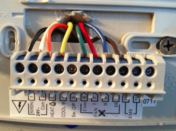
8 Wire Thermostat Wiring
The 8-wire setup can be seen very commonly in systems and it can accommodate a large number of components at the same time. It is a versatile configuration for the wiring of a system.
Let’s shed some light on the procedure and needed requirements!
[su_list icon=”icon: chevron-circle-right” icon_color=”#00cf77″]
- Wires needed: Red, white, yellow, green, black wire (for common), light blue, dark blue, orange
- Where it is found: Heat Pumps of HVAC system with Aux Heat
[/su_list]
How to wire an 8-wire thermostat
Follow these step-by-step instructions:
- For power flow (24V), connect the red wire to the R terminal.
- for the heating mode on the heat pump, connect the W (or W1) terminal with the white wire.
- AC/cooling mode will be functional by connecting the yellow wire to the Y terminal.
- The fan will be made operational by attaching the green wire to the G terminal.
- Now, you will need a spare wire for the C or Common so use the black wire for this.
- Use another wire such as the light blue wire for the auxiliary heat and connect it to the X/Aux terminal.
- The dark blue wire is to be connected to the reversing valve for heating and needs to be connected to the B terminal.
- Reversing valve for cooling is connected to the system by attaching the orange-colored wire to the O terminal.
How to use Goodman Furnace Thermostat Wiring Diagram: Step-by-Step Guide!
To use the Goodman furnace thermostat wiring here is what you need to do!
[su_list icon=”icon: chevron-circle-right” icon_color=”#00cf77″]
- Find the Diagram: You need the thermostat wiring. Here is one of the examples of wiring diagrams. Check it out!
- Identify the Wires: Now locate each wire and find out what that wire does:
- The wires on the thermostat are red = power, white = heating, yellow = cooling, and green = fan. You may also notice a blue or black wire which is the C-wire.
- The wires on the furnace are red = power, white = heating, yellow = cooling, and green = fan.
- Follow the Thermostat Wiring Guide: Carefully connect each wire correctly from the furnace to the terminals on the thermostat.
- Double-check: Go through the diagram again and review all the connections made.
- Install the Thermostat: While following the manufacturer’s instructions, set the thermostat.
- Turn the Power On: Put the power back on at the breaker box and test if the thermostat is functioning properly.[/su_list]

Where to Attach the C-wire Inside Goodman GMP100-4 Furnace
The Goodman GMP100-4 furnace is known to be an older model that may not be using a C terminal. Although, you can connect the C-wire to the furnace using the unused wire connecting it to the transformer.
Here is how you do it!
[su_list icon=”icon: check” icon_color=”#00cf77″]
- Power Off: Turn the power off to the furnace from the breaker box.
- Identify the transformer: It is located inside the furnace near the control board and looks like a small, rectangular box with wires coming out of it.
- Locate the Unused Wire: The C-wire is usually blue or black but you can use any unused wire you see here.
- Connect the Unused Wire to the C Terminal of the Thermostat: Connect the other loose end to the C terminal on the transformer inside the furnace. You can identify the C terminal on the transformer by checking the “C” or “COM”.
- Turn it On: Turn the power back on from the breaker box and test the thermostat if it is working properly.
[/su_list]
FAQ
What color is the common wire on a Goodman furnace?
How do you wire a furnace thermostat?
What happens if you connect thermostat wires wrong?
What are the R and RC wires on a thermostat?
Which wire controls furnace?
Conclusion
Performing the thermostat wire setup on the heat pump or an advanced HVAC brings forth some complications (c-wire, aux wire, etc). Take help from a goodman furnace thermostat wiring diagram.
For a basic understanding of the wiring diagram, you can easily detach and attach a new thermostat. Let us know in the comments section if the diagram and explanation solved your query. Do you have anything else about Goodman Furnace that we should discuss?