

The wiring in the RV tanks is confusing because of their many wires, colors, and specific function. In this article, we have used the RV holding tank sensor wiring diagram to describe how the wiring works if you need to fix or replace it.
You should know that there are 3 or 4 wires. Yellow signals 1/3 filled tank, green signals 2/3, orange wire signals full. In the case of 4 wires, a red wire will signal a full tank.
Having said that, you should read on for many essential things including how to monitor levels, sensor wiring tips, and common mistakes to avoid while updating the wiring.
[convertkit form=5479118]
Basics of the RV Holding Tank Sensor Wiring Diagram
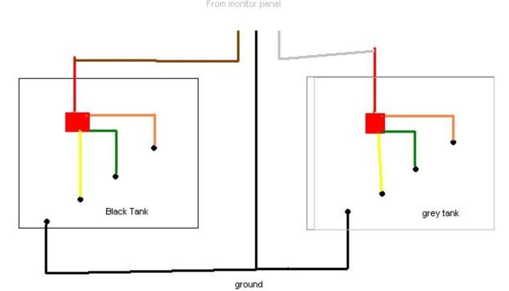
A simplified RV holding tank sensor wiring diagram underneath will help you understand the placement and colors of the wires. It is important to know the colors and what they indicate. Make sure to not switch them up when you replace the wire connections with new ones.
3 Wire Connections
Wiring in RV models can be differently routed but they all follow the same principle. If you have a tank that indicates water filling in 3 portions, the harness will have three wires on the right side of it. They are wired as:
[su_list icon=”icon: check” icon_color=”#00cf77″]
- Yellow wire indicates that the tank is almost empty, which is 1/3.
- Green indicates that the tank is more than half full, which is 2/3.
- The orange wire is used to indicate that the tank is almost full.[/su_list]
The above wires converge into a red signal wire. On the left side, a ground wire will be present, which is not attached to the harness. It can be white or grey.

4 Wire Connections
If your RV has a 4-wiring system, the monitor alerts when each quarter fills up. Let’s see how are they wired, and which color indicates, which portion.
[su_list icon=”icon: check” icon_color=”#00cf77″]
- Yellow wire indicates that the tank is 1/4 filled.
- Green wire indicates that the tank is half full, which is 2/4.
- The orange one is used to indicate that the tank filled up to 3/4 (3 quarters.)
- The red wire is used to send an alert that the tank is full.[/su_list]

What Happens in the Tank?
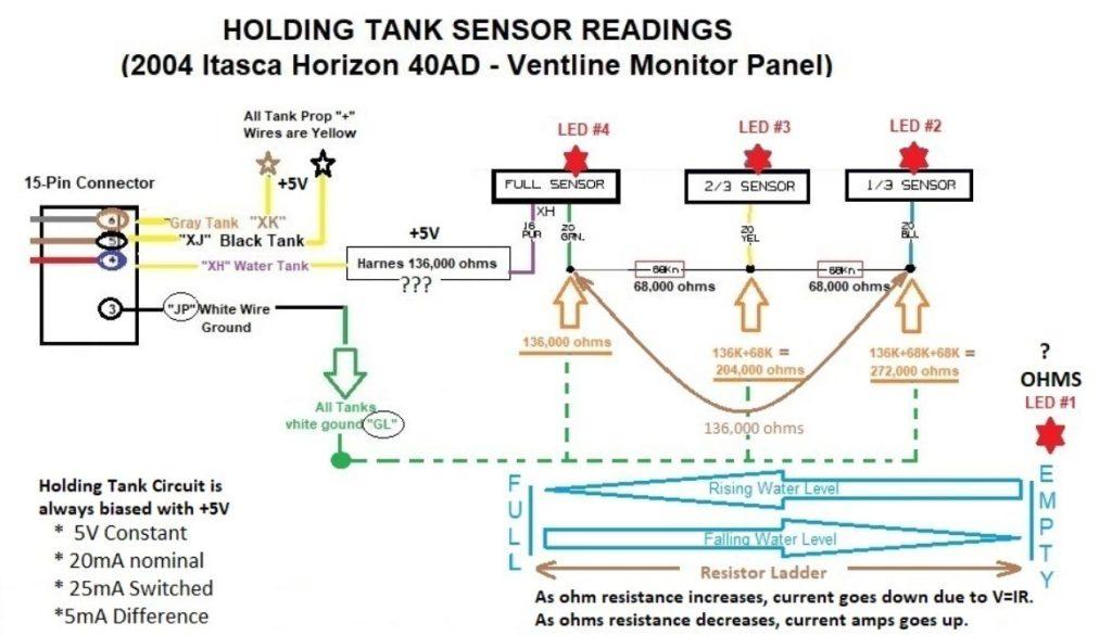
The tank level detectors rely on water or muck to complete the circuit. When the water is filled up to one of the wires, the current flows through it, and hence, the indicator light turns on.
Oftentimes, this is the reason for black and grey water holding tanks do not work well as the freshwater does. It is easier for current to pass through fresh water. The wiring diagram underneath explains this well.
How to Diagnose the Reason Behind Incorrect Reading Of Holding Tank Indicator Wiring
It could be frustrating if even one sensor does not give the correct reading of whether the tank is full or still empty. To solve this issue, perform the following steps to get to the root of it:
- Take the monitor’s panel out to view the holding tank monitor’s circuit board.
- Locate a brown wire among the 5 wires on the redhead connector.
- Disconnect the brown wire from the wiring harness.
- Check the monitor’s panel of the black tank to see if it says “empty”. Any other indication means the circuit board is flawed.
- If you find the reading “empty”, connect the brown wire back to the harness.
- At this point, disconnect the resistors network yellow, green, and orange wires from the probes.
- Separate this wiring from each other.
- Now, if the black tank display does not read “empty” it will mean there is leakage between the monitor’s brown one-wire and the resistor’s red wire connection to the harness.
- If it reads “empty” ground yellow wire to where the white ground single wire is connected to the tank. The black monitor should display 1/3 filled.
- Remove the yellow one-wire from the ground probe.
- Connect the green wire to the ground. The holding tank monitor should say 2/3 filled.
- Now you will disconnect the green one and ground an orange one for the holding tank monitor to read “full.”
If you followed the steps so far, the monitor circuit is working fine. You will need to clean the buildup attached to the black tank to get it to start working perfectly.
Fresh Water Tank: Wires Responsible for Level Indications
Freshwater holding tanks that have through-wall screw detectors can be confusing because the wires coming out of the walls that go into the connectors have different colors. Let us break it down how are they wired.
| Tanks filled | Level Sensor Wire Color | Colors at Connectors |
| 1/4 full | Red | Red or Yellow stripe |
| 2/4 full | Green | Green or Yellow stripe |
| 3/4 full | Orange | Orange or Yellow stripe |
| Completely full | Purple | Blue with Yellow stripe |
| Common wire | Black | Black or Yellow stripe |
Holding Tank’s Design: What are the Components?
We know the basics of the holding tank by now. Let’s learn the details of its structure.
Are there Screws on the Walls?
There are stainless steel screws on the walls of the tank that are attached to the coach monitor panel. These are wielded in or plugged between rubber bushings. The tails of the screws are exposed to the content of the tank.
How are the Levels Detected?
These screws are the sensors. They are placed at specific heights of the tank to report the levels. When the contents match the height of the screw, electricity flows through it to complete the circuit.
Connectors Plug Issue
The connection plug is made up of tin and pressed on a copper circuit board. These metals tend to corrode over time due to humidity. Use a corrosion blocker to avoid it.
How is a Simple Black Tank Monitoring System Wired
We have explained in our “Basics of the RV Holding Tank Sensor” how wiring works. You can also view this video to understand it better.
Alternative Ways of Sensing Tank Levels
An alternative to the through-wall and electrical sensor would be an acoustic one. They are installed inside the tank on its roof and emit acoustic waves at the surface of the holding tanks.
It learns the levels to later indicate when to alert for an empty tank and other levels. It works on any kind of content in the tank. However, it is uncommon in RV because it is very expensive and mostly used in industries.
Make Your Tank Easier for the Gunk to Slide Out
One useful tip we can share is to add a water softener to your black tanks. It will make your tank slippery without harming it. It does not contain any strong chemicals which you should avoid in order to save the tank from any damage.
Holding Tanks Are Not Always Accurate
The holding tank reading can give incorrect readings, especially the black and grey water ones. Some of the reasons could be:
[su_list icon=”icon: exclamation-circle” icon_color=”#D9091A”]
- Wires have become loose, worn out, or broken.
- Probes have gunk attached to them confusing the indicator.
- Electricity does not travel well in black and grey water as it does in freshwater.[/su_list]
How To Wire An RV’s Tank: Video
We have explained in the above sections how the wiring works and the purpose of each wire. How are you going to put your knowledge into practice? We have a video attached for a better understanding of these wires.
Holding Tank’s Sensor Wiring Tips
[su_list icon=”icon: check” icon_color=”#00cf77″]
Let’s take a look at some of the tips we have learned when working on the holding tank wirings.
- Make the connection tight, do not leave it loose, and away from the path of getting hit by something.
- Ensure there is space between the wires so that when RV moves on bumps or jolts the wires do not tangle up.
- Your RVs could be differently built so while we know the basics of holding tank wiring thoroughly look underneath the RV if there is a better wiring route.[/su_list]
[convertkit form=5479118]
RV Holding Tank Sensor Wiring Diagrams
Take a look at the additional RV Holding Tank sensor diagrams:
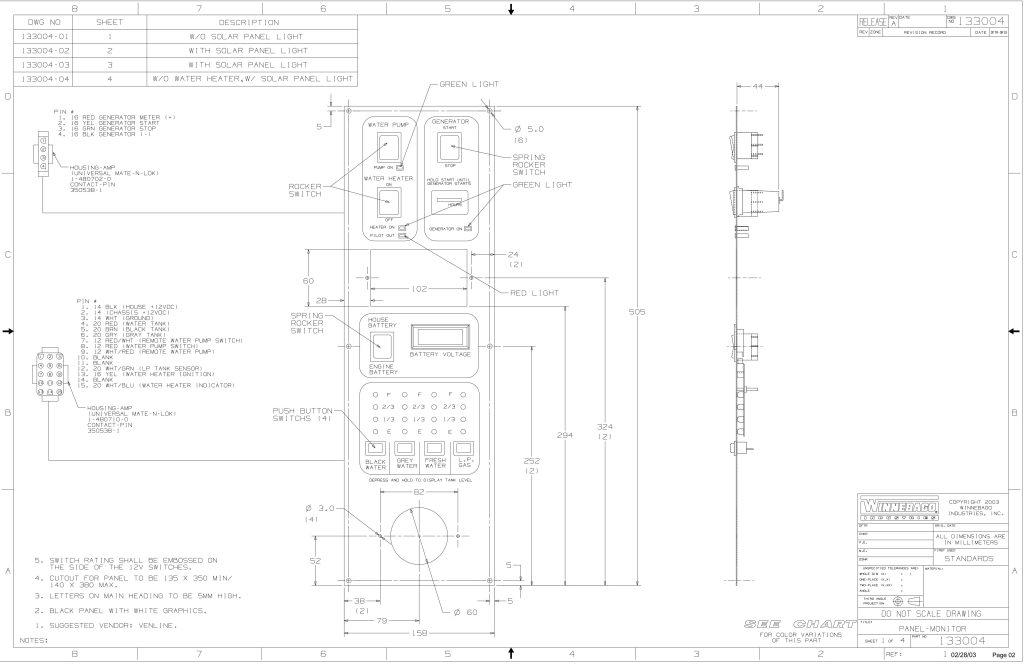
Winnebago RV Holding Tank Sensor Wiring Diagram

[su_button url=”https://camperlife.co/wp-content/uploads/2023/03/Winnebago-RV-Holding-Tank-Sensor-Wiring-Diagram-2-scaled.jpg” background=”#F53030″ color=”#f8f8ef” size=”12″ center=”yes” radius=”2″ icon=”icon: hand-o-right”]DOWNLOAD[/su_button]
[su_button url=”https://camperlife.co/wp-content/uploads/2023/03/Winnebago-Diagram-2-scaled.jpg” background=”#F53030″ color=”#f8f8ef” size=”12″ center=”yes” radius=”2″ icon=”icon: hand-o-right”]DOWNLOAD[/su_button]
Traditional Sensor-Based Tank Level Indicating Diagram

[su_button url=”https://camperlife.co/wp-content/uploads/2023/03/traditional-sensor-based-tank-level-indicating.jpg” background=”#F53030″ color=”#f8f8ef” size=”12″ center=”yes” radius=”2″ icon=”icon: hand-o-right”]DOWNLOAD[/su_button]
Tank Level Indicating Diagram

[su_button url=”https://camperlife.co/wp-content/uploads/2023/03/Tank-Level-Indicating-Diagram.jpg” background=”#F53030″ color=”#f8f8ef” size=”12″ center=”yes” radius=”2″ icon=”icon: hand-o-right”]DOWNLOAD[/su_button]
FAQ
How do RV water tank sensors work?
How do you fix an RV tank sensor?
Where are sensors located in RV holding tanks?
Why are my RV tank sensors not working?
How do I clean my RV holding tank sensors?
Conclusion
The tank has a white ground wire which is not a part of the harness, and a red signal wire that converges all the indicator wires in the connector. The yellow wires alert 1/3 level, the green alerts 2/3, and the orange alerts a full tank. If there are 4 wires, the alerts are divided into quarters and a red wire will alert the full tank.
Do not get upset if your black and gray holding tanks’ indicators are not accurate as it’s the case with most RVs. The debris gets in the way and electricity do not flow well in these as compared to freshwater ones.
What issues have you encountered with the RV holding tanks? Let us know in the comments so we can help.